2.6 Major Internal Components and Operating Principle
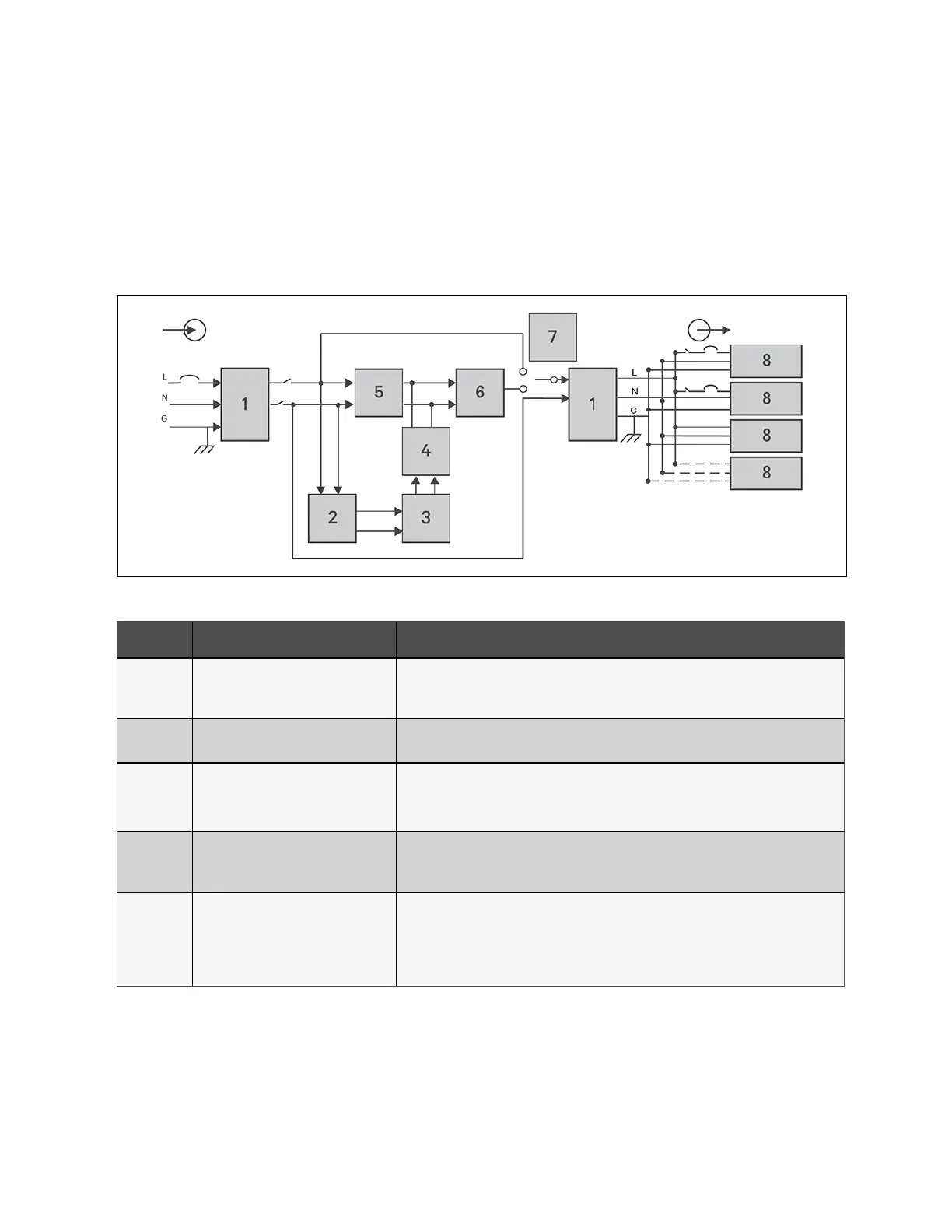
Figure 2.17 below, shows the UPS operating principle. Table 2.4 below describes the function of the major components in the
UPS.
NOTE: Figure 2.17 below, is one example of basic operation. The actual I/O connections for the various models may be
divided into different types. See Hardwired Input/Output Connections on page37.
Figure 2.17 Basic Operating Principle Diagram
Item Component Operation/Function
1
Transient Voltage Surge Suppression
(TVSS) and EMI/RFI Filters
Provide surge protection. Filter electromagnetic interference (EMI) and radio frequency
interference (RFI). Minimize surges or interference present in the utility power and protect
devices connected on the same branch as the UPS.
2 Battery Charger
Regulates input AC power to continuously float-charge the batteries. Batteries are charged
when the UPS is plugged in, even when not powered-on.
3 Batteries
Valve-regulated, non-spillable, lead-acid batteries.
NOTE: To maintain battery design life, operate the UPS in an ambient temperature of 59
°F to 77 °F (15 °C to 25 °C).
4 DC-to-DC Converter
Raises the DC voltage from the battery to the optimum operating voltage for the inverter. This
allows the inverter to operate continuously at its optimum efficiency and voltage, thus
increasing reliability.
5
Rectifier/Power Factor Correction (PFC)
Circuit
In normal operation, converts utility AC power to regulated DC power for use by the inverter
while ensuring that the wave shape of the input current used by the UPS is near ideal.
Extracting this sine-wave input current ensures efficient use of utility power and reduces
reflected harmonic distortion making cleaner power available to devices that are not
protected by the UPS.
Table 2.4 Major Components
20 Proprietary and Confidential ©2024 Vertiv Group Corp. 2 Product Description
Vertiv™ Liebert® GXT5 UPS Installer/User Guide