Unit Rating Recommended Breaker Rating
8 KVA
63 A
10 KVA
16 KVA
1-phase: 140 A
3-phase: 50 A
20 KVA
1-phase: 160 A
3-phase: 63 A
Table 3.2 Branch Circuit Breaker Rating (continued)
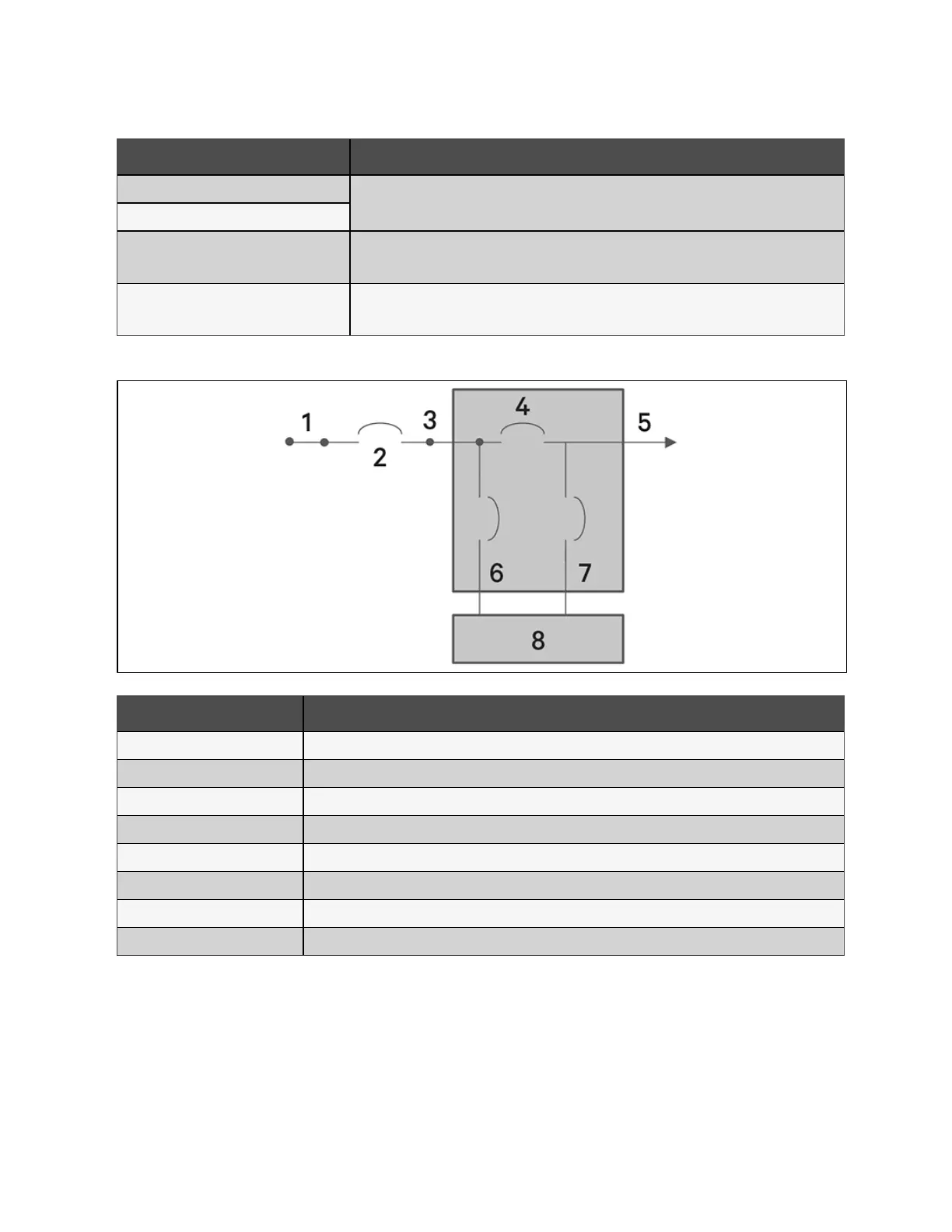
Figure 3.5 Circuit Breakers Diagram
Item Description
1 Mains/Utility
2 External Branch Circuit Breaker
3 Input
4 Maintenance Bypass Circuit Breaker
5 Output
6 Input Circuit Breaker
7 Output Circuit Breaker
8 UPS-PFC, battery inverter
3.6.2 Terminal Block Connections
On 5 kVA to 20 kVA models, the hard wire connections to the terminal blocks are made through knockouts on the POD
attached to the rear of the unit. See Removable Power Distribution Box on page16, for the location of the input/output
knockouts on your Vertiv™ Liebert® GXT5 model. Models below 3000 VA use input cords with plugs instead of terminal block
connections.
Table 3.3 on the facing page details the electrical connection specifications.
38 Proprietary and Confidential ©2024 Vertiv Group Corp. 3 Installation
Vertiv™ Liebert® GXT5 UPS Installer/User Guide