Liebert Trinergy™ Cube MECHANICAL INSTALLATION
Page 62 Installation Manual - 10H52243IM60 - rev. 7 - 06/2020
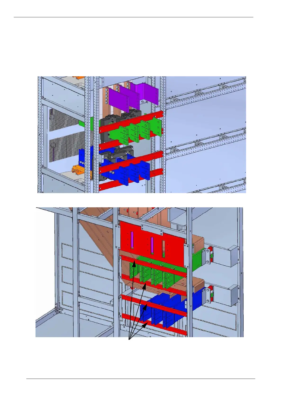
The figures explaining how to assemble the bus-bars on the static cabinet with the ones on the I/O box
are found below.
• Use contact grease for the correct connection and installation of the bus-bars.
• The three different colours (purple, green, blue) show the three different sets of bus-bars that
have to be connected together (purple with purple, green with green, blue with blue)
• The screw can be inserted from both sides. Always check that the safety distance of 20mm
between phase is always present after the assembly.
Figure 64 - STEP 3 - Bus-bars of the static cabinet for the assembly with the bus-bars on the I/O
cabinet. Do not remove the vetronite (red).
Figure 65 - STEP 4 - To facilitate the assembly of the bus-bars of the I/O cabinet with the
bus-bars on the static cabinet, the vetronite (red) can be removed only on this box.
TO FACILITATE THE assembly, REMOVE THIS MATERIAL
 Loading...