EasyManuals Logo

Vertiv Liebert Trinergy Cube Installation Manual

Vertiv Liebert Trinergy Cube
136 pages
To Next Page IconTo Next Page
To Previous Page IconTo Previous Page
Page #69 background imageLoading...
Page #69 background image
Liebert Trinergy™ Cube MECHANICAL INSTALLATION
Page 68 Installation Manual - 10H52243IM60 - rev. 7 - 06/2020
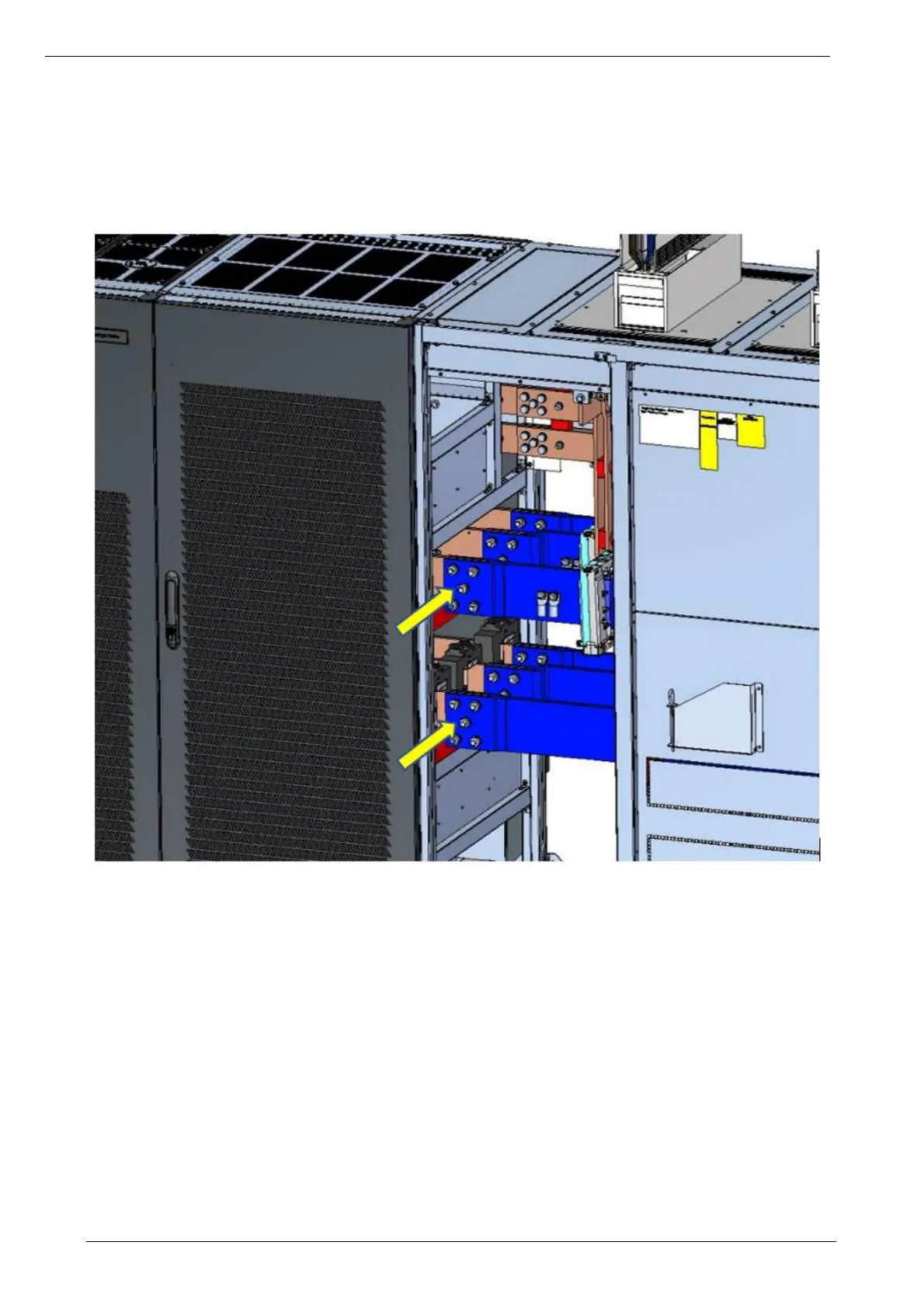
The screw can be inserted from both sides. Always check that the safety distance of 20mm between
phase is always present after the assembly. Bus-bars of the static cabinet for the assembly with the bus-
bars on the I/O cabinet. Do not remove the vetronite.
N. 30 SCREWS M16x70 with FLAT WASHER + N. 30 NUT M16 with FLAT and GROWER (5x to be used
on each bar connection)
Figure 72 - STEP 4 - Bus-bars connections - FRONT VIEW

Table of Contents

Other manuals for Vertiv Liebert Trinergy Cube

Questions and Answers:

Question and Answer IconNeed help?

Do you have a question about the Vertiv Liebert Trinergy Cube and is the answer not in the manual?

Vertiv Liebert Trinergy Cube Specifications

General IconGeneral
BrandVertiv
ModelLiebert Trinergy Cube
CategoryUPS
LanguageEnglish

Related product manuals