With reaching the comparison condition the hysteresis
gets active
and a pulse of the parameterized duration is put out. As long as the
counter value is within the hysteresis range, no other pulse is put out.
With activating the hysteresis the counting direction is stored in the
module. If the counter value leaves the hysteresis range
contrary to
the stored counting direction, a pulse of the parameterized duration is
put out. Leaving the hysteresis range without direction change, no
pulse is put out.
6.6
Frequency measurement
6.6.1 Overview
In this operating mode the CPU counts the incoming pulses during a
specified integration time and outputs them as frequency value. You
can set a value for the integration time between 10ms and 10000ms,
in steps of 1 ms. You can set the integration time in the parameter
assignment screen forms or you can edit them in the job interface of
the SFB FREQUENC (SFB 48).
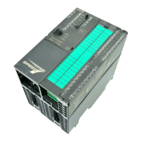
1 Integration time
2 Count pulse
3 Internal gate (SW gate)
4 Start of frequency measurement
5 Stop of frequency measurement
The measurement is carried out during the integration time and is
updated after the integration time has expired If the period of the
measured frequency exceeds the assigned integration time, this
means there was no rising edge during the measurement, a value of
0 is returned. The calculated frequency value is supplied in "mHz"
units. You can read out this value with the SFB parameter
MEAS_VAL. The number of activated channels does not influence
the max. frequency, which is defined in the technical data.
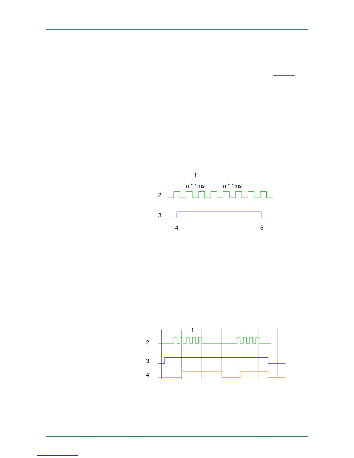
1 Integration time
2 Count pulse
3 Internal gate (SW gate)
4 Calculated frequency
Measuring procedure
VIPA System 300SDeployment I/O periphery
Frequency measurement > Overview
HB140 | CPU-SC | 313-6CF13 | GB | 15-50 126