6.4 Digital part
The digital part consists of 16 input, 16 output and 3 channels for
technological functions. Each of these digital input- respectively
output channels shows its state via a LED. By means of the parame-
terization you may assign interrupt properties to the inputs I+0.0 to
I+1.7.
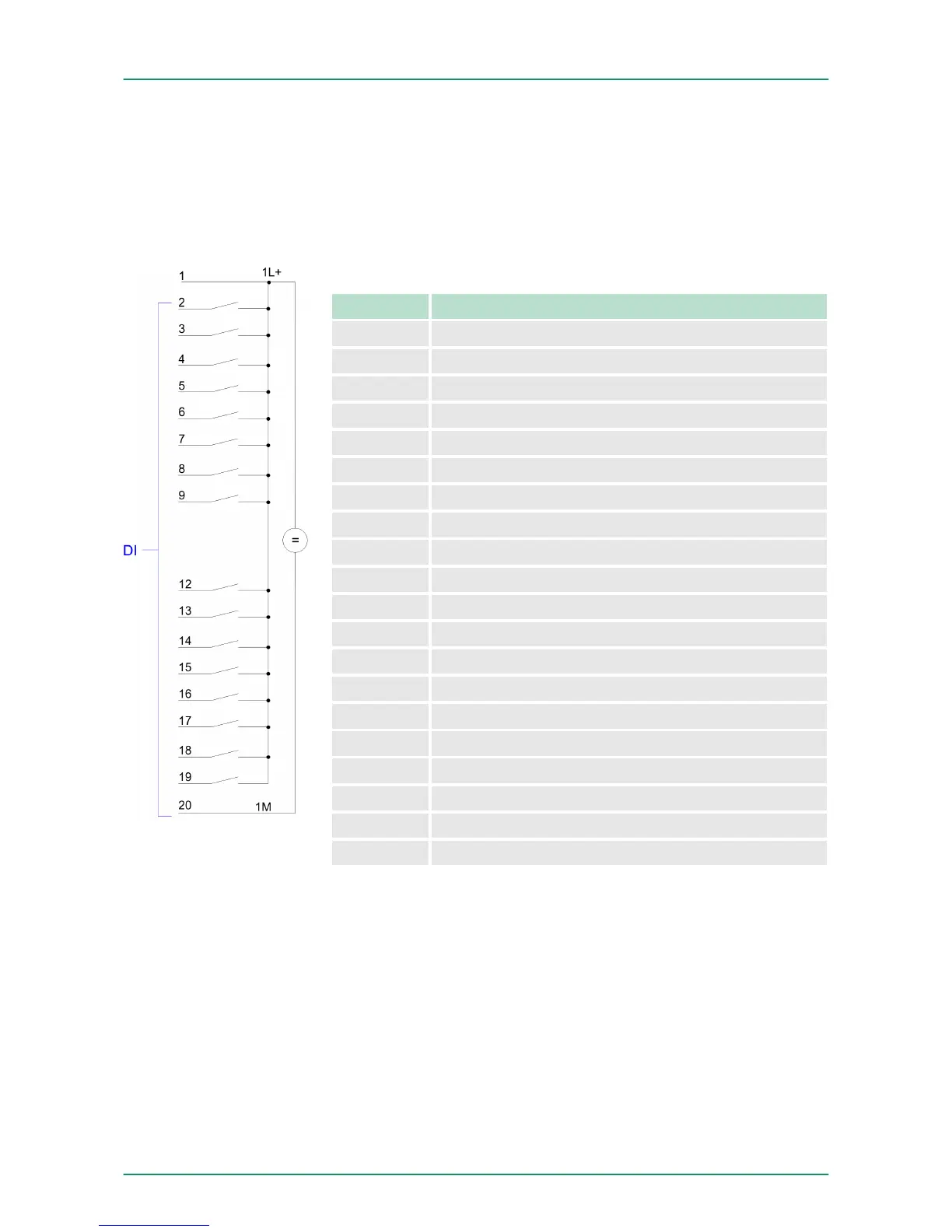
Pin assignment X11: DI
Pin Assignment
1 1L+ Power supply +DC 24V
2 I+0.0 / Channel 0 (A) / Pulse
3 I+0.1 / Channel 0 (B) / Direction
4 I+0.2 / Channel 0 HW gate
5 I+0.3 / Channel 1 (A) / Pulse
6 I+0.4 / Channel 1 (B) / Direction
7 I+0.5 / Channel 1 HW gate
8 I+0.6 / Channel 2 (A) / Pulse
9 I+0.7 / Channel 2 (B) / Direction
10 not used
11 not used
12 I+1.0 / Channel 2 HW gate
13 I+1.1
14 I+1.2
15 I+1.3
16 I+1.4 / Channel 0 Latch
17 I+1.5 / Channel 1 Latch
18 I+1.6 / Channel 2 Latch
19 I+1.7
20 Ground 1M DI
313-6CF13
VIPA System 300S Deployment I/O periphery
Digital part
HB140 | CPU-SC | 313-6CF13 | GB | 15-50 101