95x Series Operating Manual - May 17, 2022
Page 103 of 155
SECTION 8 – DIO INTERFACE
Using the 95x Digital Input & Output (DIO) interface the user may perform any combination of the following –
• Control the 95x using a PLC type device, starting, stopping, selecting a sequence, and determining the
pass/fail status
• Control the 95x using external start and/or stop switches
• Abort a test sequence when a safety interlock is opened
• Allow the 95x to illuminate external safety indicators
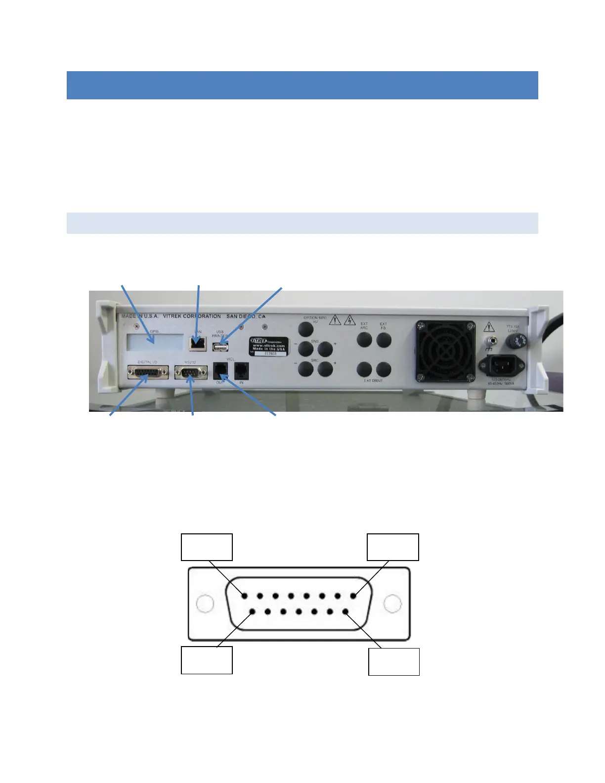
CONNECTOR AND PINOUT
The DIO signals are available at the rear panel of the 95x in the 15-pin connector identified as “DIGITAL I/O” as
shown the photograph above. The 95x connector is a standard two-row 15-pin female Dsub connector; any
suitable male mating connector may be used.
The diagram below shows the pin locations within the connector as viewed from the rear panel of the 95x.