95x Series Operating Manual - May 17, 2022
Page 133 of 155
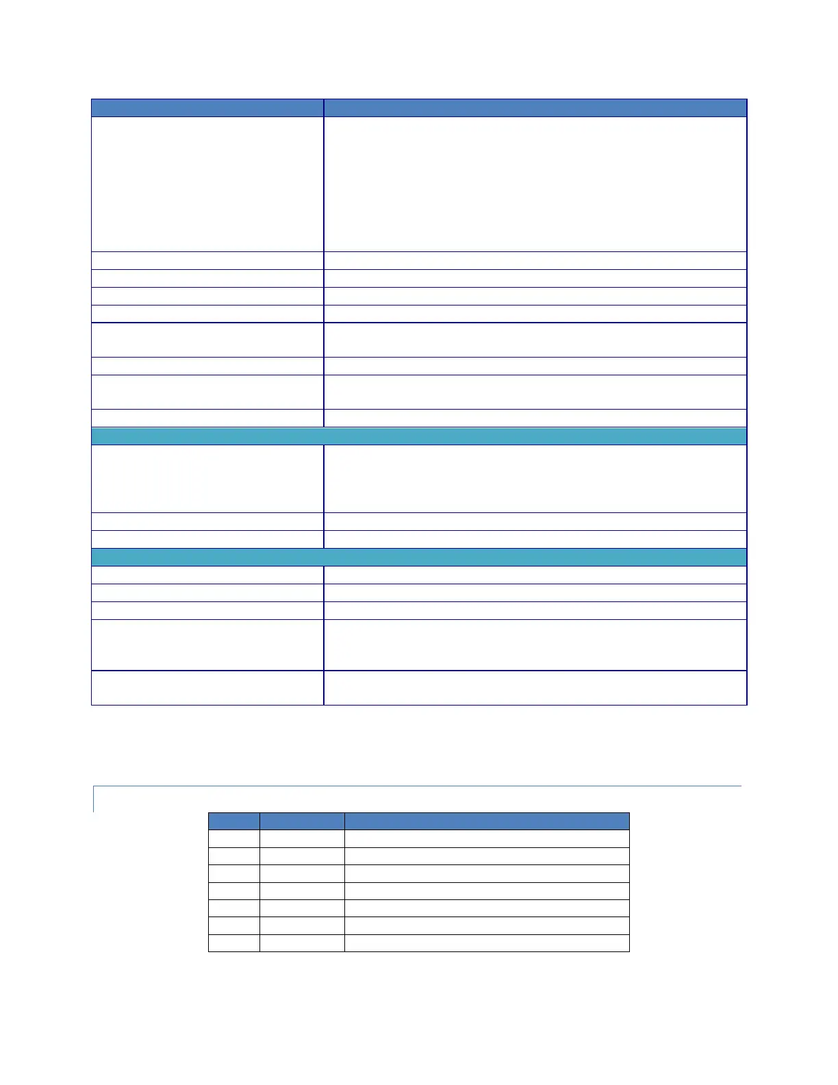
Configures the switch matrix unit control setting.
NONE – no external switch matrix units
948 – a single 948i using RS232
964SER – a single 964i using RS232
964VICL1 – a single 964i using VICL
964VICL2 – two 964i using VICL
964VICL3 – three 964i using VICL
964VICL4 – four 964i using VICL
Responds with the <STRING> switch matrix unit control setting
Sets the present time (hours, minutes, seconds)
Configures the clock 12/24hr configuration setting
Responds with the <BOOL> clock 12/24hr configuration setting
Configures the maximum DC Voltage available during future test
sequences
Responds with the <NR3> maximum DC Voltage setting
Configures the maximum AC Voltage available during future test
sequences
Responds with the <NR3> maximum AC Voltage setting
Responds with a set of fields describing the product, see
*IDN? Response Fields
Responds with a set of <STRING> fields indicating each installed option
Responds with a <STRING> indicating the serial number of the product
Responds with the present date as a <STRING> (mm/dd/yy)
Sets the front panel into the LOCAL state
Sets the front panel into the REMOTE LOCK-OUT state
Resets all interfaces
Aborts a running test sequence
Clears the active test sequence
Responds with the present time as a <STRING> (hh:mm:ss)
This is always in 24hr format
Manufacturer (e.g., VITREK)
Serial number (e.g., 123456)
Main firmware version (e.g., v1.45)
Front panel firmware version (e.g., v1.21)
Measurement DSP firmware version (e.g., v1.21)
Drive DSP firmware version (e.g., v1.21)