95x Series Operating Manual - May 17, 2022
Page 72 of 155
o BIPOLAR. A pair of opposite polarity pulses of voltage is produced.
• BREAKDOWN. Allows breakdown detection to be programmed as a maximum peak current level. Note
that the maximum drive current during testing is limited by the test voltage and the 95x output
impedance (see Specifications), entering a value higher than can be achieved renders this setting inactive.
• RAMP. See figures in Actions While Running. The minimum value is 1ms (0.5ms if Opt. AC-2 if installed),
and the maximum value is 20ms.
• HOLD. See figures in Actions While Running. The minimum value is 1ms (0.5ms if Opt. AC-2 if installed),
and the maximum value is 30ms.
• ARC DETECT. Allows the user to program arc detection during this step. Both the time and current level
can be independently programmed. Arc detection can also be disabled by setting the leftmost (time)
setting to OFF. The 95x can be configured to not fail a test step when arcing is detected by setting the
ARC setting in the CNFG – TEST sub-menu to DETECT ONLY.
• ON FAIL. This allows the user to program the 95x to abort the entire sequence (ABORT SEQ) or only this
step (CONT SEQ) if this step fails any of its checks. A safety related failure or a user abort (STOP button)
always aborts the entire sequence.
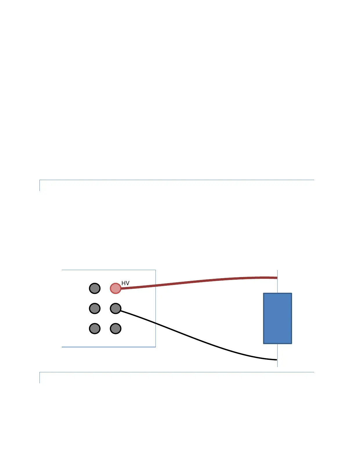
CONNECTING TO THE DUT
See Terminals and Wiring for general wiring and safety recommendations.
The 95x requires that the DUT (at least that portion which is being measured) is isolated from ground.
The DUT should be wired between the HV and RETURN terminals of the 95x.
The 95x provides a safety ground termination for the DUT during the test via its RETURN terminal. When deciding
which point on the DUT to connect to the HV terminal and which point to connect to the RETURN terminal, the
user should consider that only the voltage on the RETURN terminal is safe at all times.
LEAD COMPENSATION
This type of test step uses the Lead Compensation feature of the 95x in a different way to all other types as it does
not compensate for any cabling effects, but instead compensates for the loading effect on the 95x caused by the
load resistance. The output voltage level from the 95x cannot be accurately controlled for this type. The output
impedance when running this type is of significance, refer to Specifications.