95x Series Operating Manual - May 17, 2022
Page 79 of 155
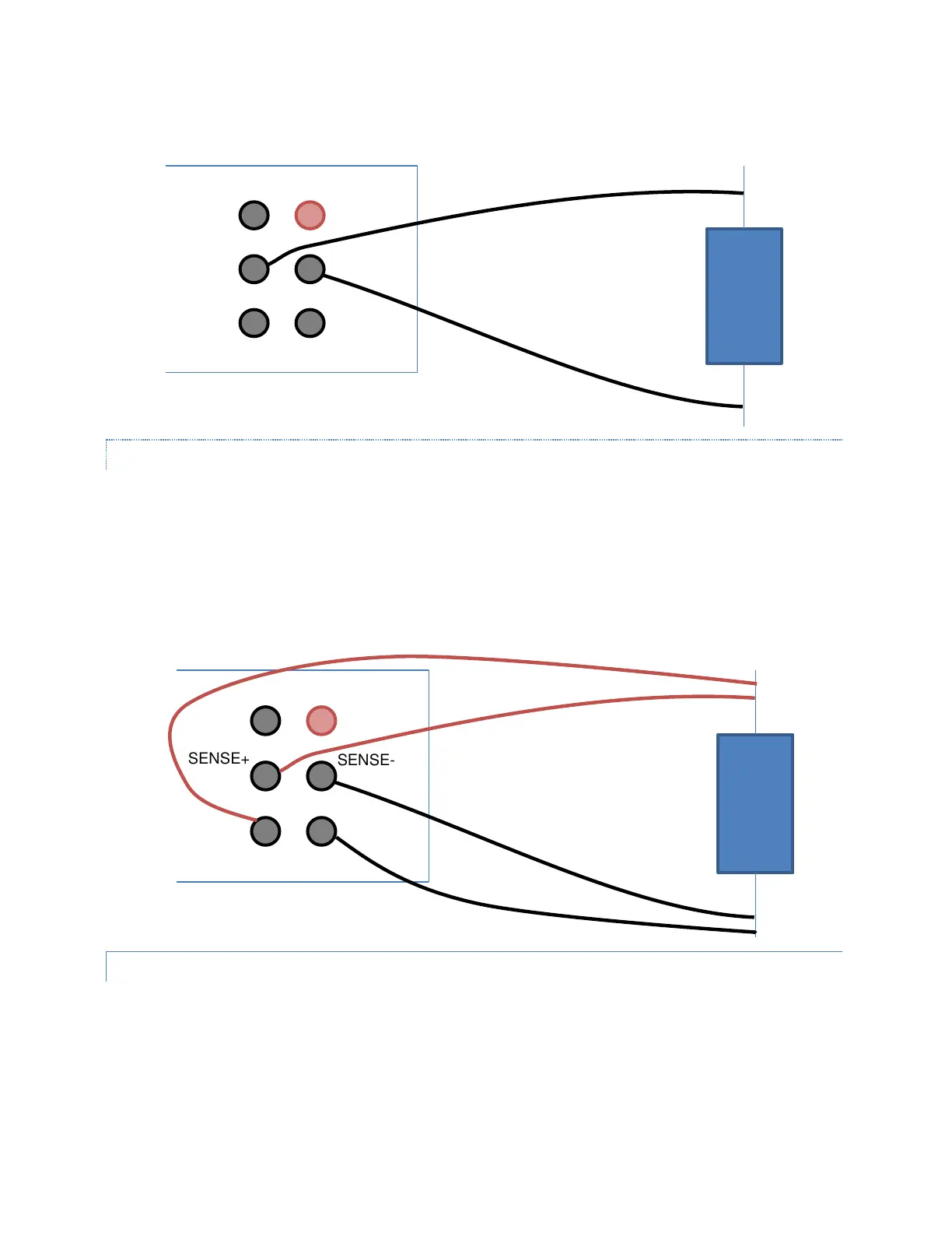
4-WIRE MEASUREMENT CONNECTIONS
When making 4-terminal measurements the resistance of the wires, the contact resistance to the DUT, and the
contact resistance within the 95x front panel terminals are not included in the result, the only recommendation is
that the SOURCE+ and SOURCE- wires be of sufficient gage to withstand the 50mA test current. When wired as
shown below, the actual resistance measured is that between the innermost connection points to the DUT (i.e.,
between the SENSE+ and SENSE- connections).
If any wire has more than nominally 100Ω of resistance, then the test is failed with a WIRING FAULT condition.
LEAD COMPENSATION (2-WIRE)
Performing a lead compensation for this type of test step compensates for lead resistance.
During a lead compensation the SENSE+ and SENSE- wires should be solidly shorted together at the DUT end, the
95x will then measure the lead resistance and automatically subtract it from all future measurements.