95x Series Operating Manual - May 17, 2022
Page 119 of 155
• Press START to perform the verification.
• Press STOP to abort the entire sequence.
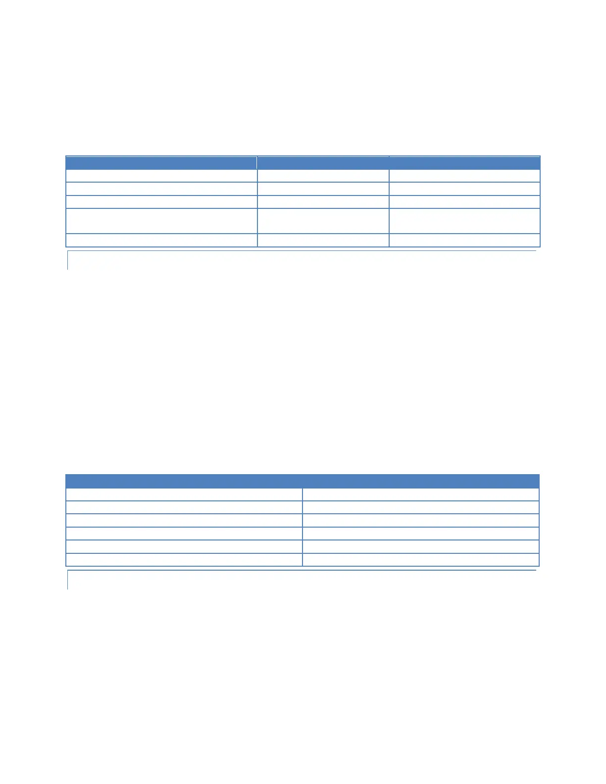
During each step, the user should note the displayed current and record it, checking against the 95x specification
shown in the table below. When the user is satisfied that the step has been completed, the user should press
START to continue or STOP to abort the sequence.
Voltage Level/Frequency/Parameter
All except 956i, 959i and if
opt. AC2 not fitted
LOW OHMS RESISTANCE VERIFICATION
The user should connect the prompted value resistance standard (equipment #4, 5 and 6 in the equipment list
above) to the SENSE and SOURCE terminals of the 95x using a 4-wire connection method for all but the final step
in this part of the sequence (which should be a 2-wire connection to the SENSE terminals only). For all 4-wire
connections the 95x internal current source is from the SOURCE terminals, and the voltage sense uses the SENSE
terminals, ensure that the resistor is connected with the + terminals and – terminals correctly paired for a 4-wire
measurement.
The table below shows the listing of the resistances requested for verification and the 95x specification at each
resistance value. When prompted for each step the user should either –
• Press the START switch to perform the verification.
• Press the STOP switch to abort the entire sequence.
During each step, the user should note the displayed resistance measurement on the 95x display and record it,
checking against the 95x specification shown in the table below. When the user is satisfied that the step has been
completed, the user should press START to continue or STOP to abort the sequence.
GROUND BOND VERIFICATION
This series of steps is only included in the 952i, 954i and 959i models.
The user should connect the prompted value resistance standard (equipment #7 in the equipment list above) to
the SENSE and SOURCE terminals of the 95x using a 4-wire connection method. For all 4-wire connections the 95x
internal current source is from the SOURCE terminals, and the voltage sense uses the SENSE terminals, ensure that
the resistor is connected with the + terminals and – terminals correctly paired for a 4-wire measurement. The user
should also ensure that the cabling to the SOURCE terminals of the 95x is capable of handling the measurement
current shown. To reduce cross-coupling between the SOURCE and SENSE wiring, the user is recommended to use
one twisted pair for the SOURCE connections and a separate twisted pair for the SENSE connections.