95x Series Operating Manual - May 17, 2022
Page 85 of 155
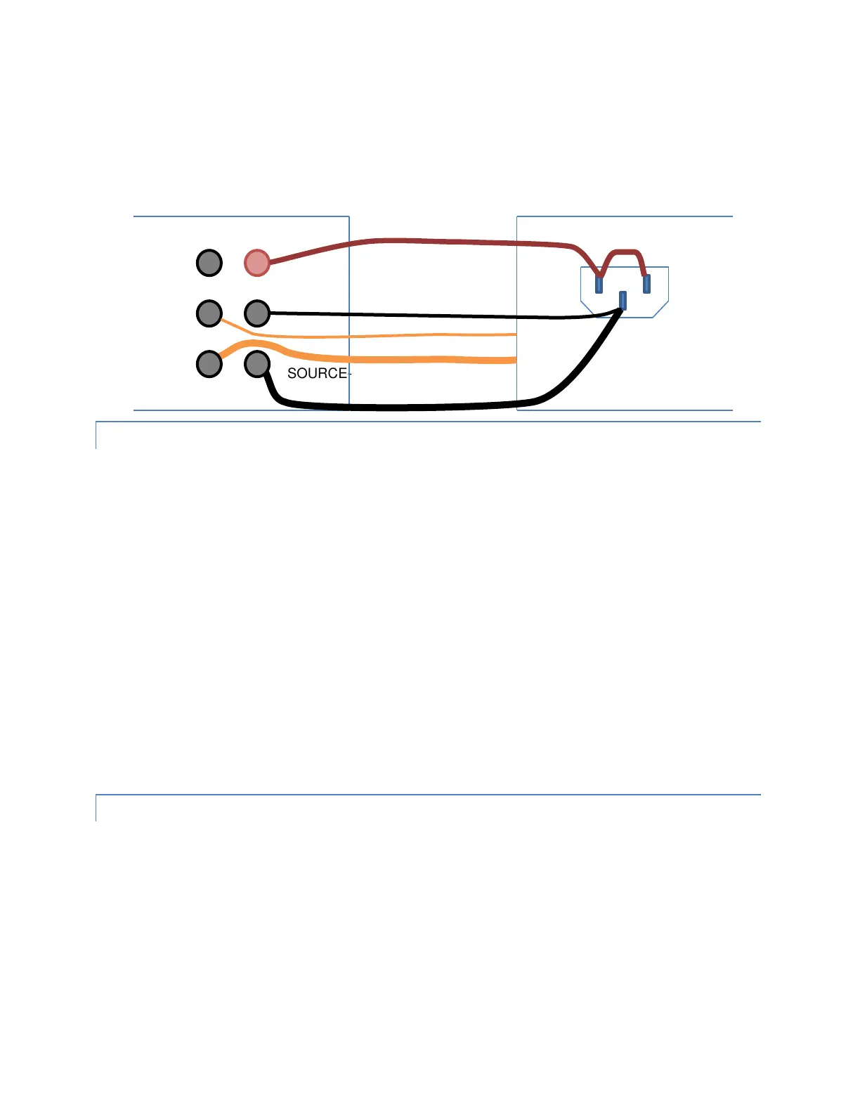
The example below shows the connections to a DUT to perform a DC or AC withstand test on the Line/Neutral line
power input, and an AC Ground Bond test on the chassis of the DUT in the same sequence. If wired in this manner,
then no changes in connections are needed.
LEAD COMPENSATION
Lead Compensation is not usually performed when using a 4-wire measurement since lead resistance is
automatically eliminated. If the DUT is connected in a 2-wire manner (e.g., separate wires for SOURCE and SENSE,
but they are shorted together before the connection to the DUT) then a Lead Compensation may be performed to
offset the resistance of the common wiring in future runs.
Lead Compensation should be used with caution to offset errors caused by inductive coupling between the wiring;
the inductive coupling effect is not strictly an offset error as it varies with the DUT resistance and reactance, and
the use of Lead Compensation could introduce significant errors.
When performing a lead compensation, the impedance limits are not enforced, otherwise the test step is executed
normally.
During a lead compensation the SOURCE+, SENSE+, SOURCE- and SENSE- wires should be solidly shorted together
at the DUT end, the 95x will then measure the resistance and reactance and will automatically subtract them from
all future measurements.
For reference, a near perfect 4-terminal short circuit can be created by connecting the leads to the same short,
straight, length of heavy gage conductor in the order SOURCE+, SOURCE-, SENSE+ and then SENSE-. This creates
the situation where there is no current flow in the DUT between the SENSE terminals, so there is no measurable
impedance between them. The effective impedance of this connection is well below 1uΩ at line frequencies.
EXAMPLES
Example 1 -
It is required to test that a DUT chassis is bonded to its grounding terminal with no more than 2.5V drop at 25Arms
when tested for at least 30 seconds.
This is accomplished in a single step as follows –
Seq 1 Step 1 GBez No ramp or discharge, RMS limits, so use GBez
LEVEL:25.000A 60.0Hz As required
DWELL: 30.0sec As required
Lim: 0u-2.5000V As required
ON FAIL: ABORT SEQ