13
Horizontal
position knob
Moves the waveform horizontally
(page54).
TIME/DIV knob
TIME/DIV
Selects the horizontal scale
(page54).
Vertical position
knob
Moves the waveform vertically
(page58).
CH1/CH2 key
CH 1
Configures the vertical scale and
coupling mode for each channel
(page58).
VOLTS/DIV knob
VOLTS/DI
Selects the vertical scale (page58).
Input terminal
CH1
Accepts input signals: 1MΩ±2%
input impedance, BNC terminal.
Ground terminal
Accepts the DUT ground lead to
achieve a common ground.
MATH key
T
Performs math operations (page46).
SD card
connector
Facilitates transferring waveform
data, display image, and panel
settings (page71).
Probe
compensation
output
Outputs a 2Vp-p, square signal for
compensating the probe (page91)
or demonstration.
External trigger
input
EXT TRI
Accepts an external trigger signal
(page61).
Power switch
Powers the oscilloscope on or off.
DSO-4000 User Manual
14
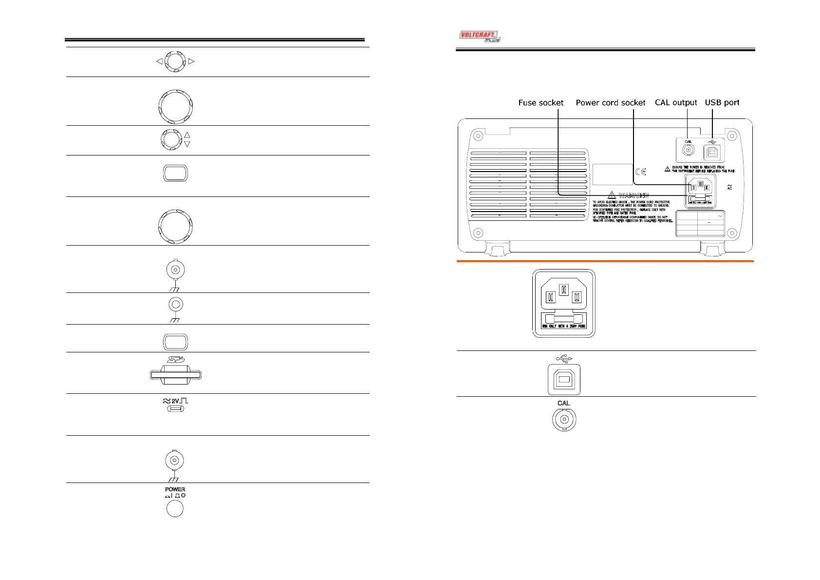
Rear Panel
LI NE VOLTAGE
AC 100 240V
FUSE RATING
RAN GE
T1A 250 V
FREQUENCY
50 60Hz
POWER MAX .
18W 40VA
Power cord
socket
Fuse socket
Power cord socket accepts the AC
mains, 100 ~ 240V, 50/60Hz.
Fuse socket holds the AC main
fuse, T1A/250V.
For fuse replacement procedure,
see page95.
USB slave port
Accepts a type B (slave) male USB
connector for remote controlling
the oscilloscope (page69).
Calibration
output
Outputs the calibration signal used
in vertical scale accuracy calibration
(page90).