Do you have a question about the WAGO PFC200 2ETH RS XTR and is the answer not in the manual?
Specifies applicability of the documentation to the PFC200 controller and firmware version.
Details copyright protection for the manual, figures, and illustrations.
Covers subject to changes, personnel qualifications, and compliance with provisions.
Provides essential safety precautions for installing and operating the device.
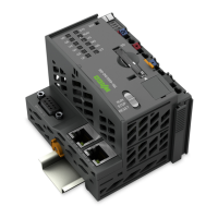
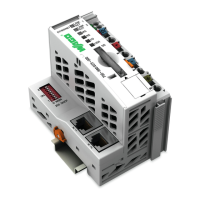
Provides a visual overview of the controller's components and their functions.
Details the various connectors for data, power, and communication interfaces.
Explains the function of power supply and system indicating elements (LEDs).
Provides detailed technical specifications for the device and system.
Covers network interface configuration, security, and services like DHCP and DNS.
Explains the usage, formatting, backup, and restore functions of the memory card.
Describes the approved mounting positions for the WAGO I/O SYSTEM 750 XTR.
Explains properties of carrier rails and guidelines for optimal system setup.
Describes the procedure for snapping modules onto a carrier rail and potential errors.
Details power jumper contacts for field-side power supply and associated risks.
Explains the system and field power supply requirements, including fuse protection and voltage sources.
Explains the importance of shielded cables for reducing interference and improving signal quality.
Details the procedure and indicators for switching on the controller and connected I/O modules.
Describes default IP addresses and how to adapt IP addressing for PC and controller communication.
Provides instructions and recommendations for changing default passwords for enhanced security.
Outlines the available methods for configuring the controller: WBM, CBM, CODESYS, and WAGO Ethernet Settings.
Provides step-by-step instructions for installing the CODESYS 2.3 programming software.
Explains how to configure the PLC for I/O modules and declare variables.
Illustrates how to edit a program function block, including assigning inputs to outputs.
Details the steps for loading and running a PLC program in the controller via ETHERNET.
Describes how to set task response and priority in the task configuration.
Provides additional information on installation, startup, and programming for e!COCKPIT and CODESYS 3.
Details the sizes of memory spaces for program, data, flags, and retain variables.
Introduces Modbus as an open fieldbus standard and its protocol architecture.
Explains how to configure Modbus operating modes using CODESYS PLC configuration.
Describes Modbus data exchange methods and relevant address areas in the PFC200.
Explains the Modbus process images for PLC and Modbus interface data exchange.
Provides an overview of Modbus address areas for PFC-OUT, PFC-IN, and special registers.
Lists WAGO Modbus registers including watchdog, status, electronic label, and network configuration.
Explains the Modbus watchdog function, operation modes, and state transitions.
Describes operating and status messages indicated by LEDs for power supply and fieldbus/system.
Explains how to interpret diagnostic messages indicated by flashing sequences on LEDs.
Provides detailed instructions for inserting and removing the SD memory card.
Covers firmware upgrade and downgrade procedures, including important notices.
Details the procedure for performing a factory reset, including data overwriting warnings.
Provides instructions for removing devices, including safety precautions and specific steps for the fieldbus coupler/controller.
Explains the procedure for removing an I/O module from the assembly.
Shows marking examples for Europe according to ATEX and IECEx.
Details installation regulations for hazardous areas, including explosion protection notes.
Describes the process image representation for WAGO I/O SYSTEM 750 XTR modules and process value configuration.
Explains digital input modules, their process value mapping, and diagnostic bits.
Details digital output modules, their mapping, and diagnostic bits for overload or short circuits.
Describes analog input modules, their measured data, and control/status bits mapping.
Explains analog output modules, their output values, and control/status bits mapping.
Lists general CODESYS system libraries supported by the controller.
| Processor | ARM Cortex-A8 |
|---|---|
| Clock Speed | 600 MHz |
| RAM | 256 MB |
| Ethernet Ports | 2 |
| Protection Class | IP20 |
| Power Supply | 24 V DC |
| Serial Ports | 1 (RS-232/RS-485) |
| Operating Temperature | -40°C to +70°C |
| Programming Languages | IEC 61131-3 |
| Certifications | UL |