WAGO I/O SYSTEM 750 XTR Table of Contents 3
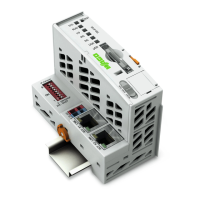
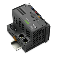
750-8202/040-000 PFC200 2ETH RS XTR
Manual
Version 1.2.0, valid from FW Version 03.01.07(13)
Table of Contents
1 Notes about this Documentation ............................................................ 15
1.1 Validity of this Documentation ................................................................ 15
1.2 Copyright................................................................................................ 15
1.3 Symbols ................................................................................................. 16
1.4 Number Notation .................................................................................... 17
1.5 Font Conventions ................................................................................... 17
2 Important Notes ........................................................................................ 18
2.1 Legal Bases ........................................................................................... 18
2.1.1 Subject to Changes ........................................................................... 18
2.1.2 Personnel Qualifications.................................................................... 18
2.1.3 Use of the 750 Series in Compliance with Underlying Provisions ..... 18
2.1.4 Technical Condition of Specified Devices ......................................... 19
2.1.4.1 Disposal ........................................................................................ 19
2.1.4.1.1 Electrical and Electronic Equipment ........................................ 19
2.1.4.1.2 Packaging ................................................................................ 20
2.2 Safety Advice (Precautions) ................................................................... 21
2.3 Licensing Terms of the Software Package Used ................................... 24
2.4 Special Use Conditions for ETHERNET Devices .................................. 24
3 Device Description ................................................................................... 26
3.1 View ....................................................................................................... 29
3.2 Labeling ................................................................................................. 31
3.2.1 Manufacturing Number ...................................................................... 31
3.3 Connectors ............................................................................................. 32
3.3.1 Data Contacts/Local Bus ................................................................... 32
3.3.2 Power Jumper Contacts/Field Supply ............................................... 33
3.3.3 CAGE CLAMP
®
Connectors .............................................................. 34
3.3.4 Service Interface ............................................................................... 35
3.3.5 Network Connectors .......................................................................... 36
3.3.6 Communication Interface .................................................................. 37
3.3.6.1 Operating as an RS-232 Interface ................................................ 38
3.3.6.2 Operating as an RS-485 Interface ................................................ 39
3.4 Display Elements ................................................................................... 40
3.4.1 Power Supply Indicating Elements .................................................... 40
3.4.2 Fieldbus/System Indicating Elements ............................................... 41
3.4.3 Memory Card Indicating Elements .................................................... 42
3.4.4 Network Indicating Elements ............................................................. 43
3.5 Operating Elements ............................................................................... 44
3.5.1 Operating Mode Switch ..................................................................... 44
3.5.1.1 CODESYS 2 Runtime System ...................................................... 44
3.5.1.2 e!RUNTIME Runtime System ....................................................... 44
3.5.2 Reset Button ..................................................................................... 45
3.6 Slot for Memory Card ............................................................................. 46
3.7 Schematic Diagram ................................................................................ 47
3.8 Technical Data ....................................................................................... 48
3.8.1 Device Data ....................................................................................... 48
3.8.2 System Data ...................................................................................... 48
 Loading...