SSW7000 | 5-27
Installation and Connection
■ Minimum insulation voltage of the cables according to the power supply.
Commercial examples: Cofiban – Cofialt, Pirelli – Eprotenax, Ficap – Fibep.
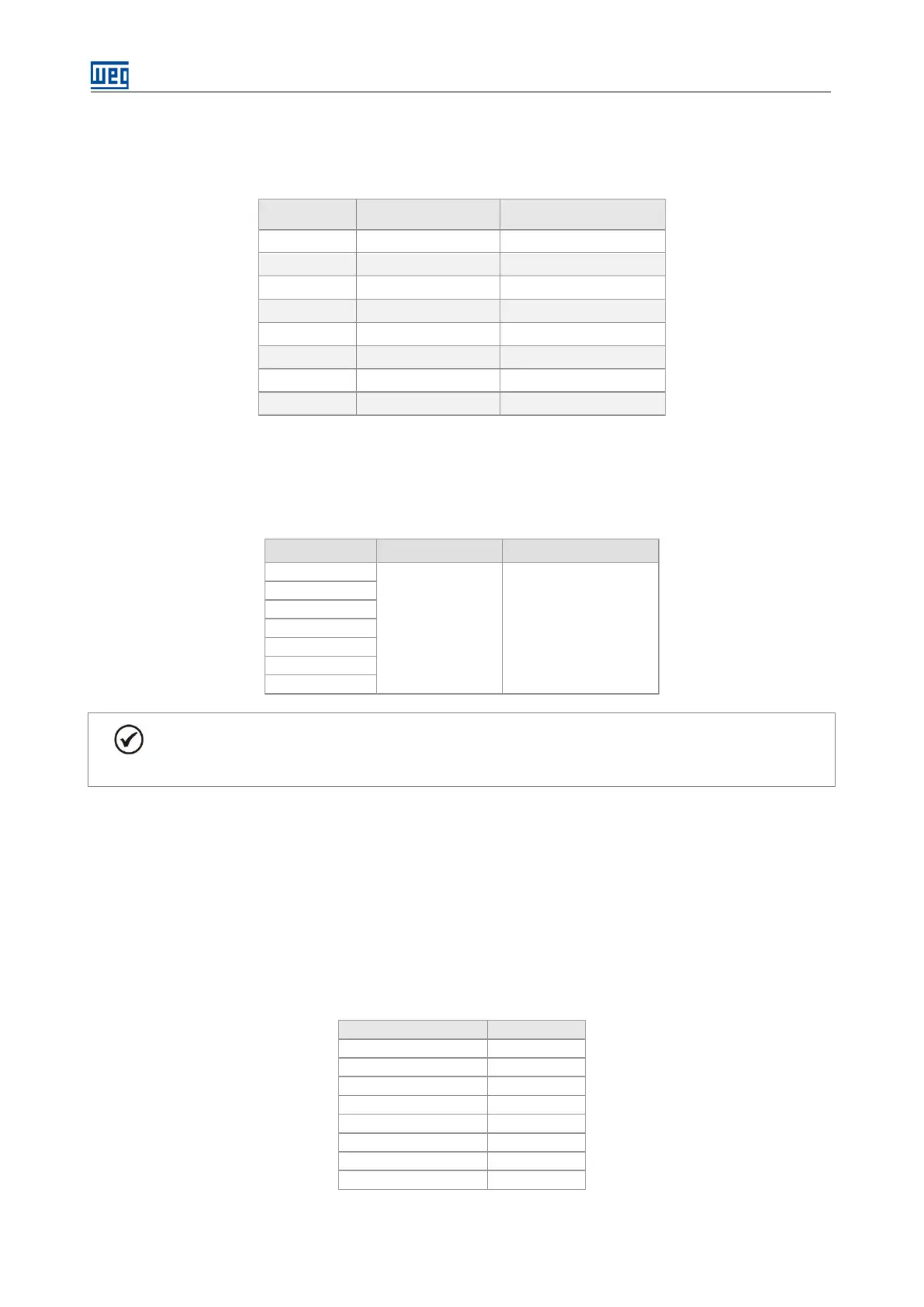
Table 5.19: Recommended cable for 100 % of the rated current
Power Cable Cross
Section mm² (in²)
Grounding Cable Cross
Section mm² (in²)
70 A 35 (0,06) 25 (0.04)
125 A 50 (0.08) 25 (0.04)
180 A 70 (0.11) 35 (0.05)
250 A 150 (0.24) 95 (0.15)
300 A 185 (0.29) 95 (0.15)
360 A 240 (0.37) 120 (0.19)
500 A 2 x 150 (2 x 0.24) 2x 95 (2 x 0.15)
600 A 2 x 185 (2 x 0.29) 2x 95 (2 x 0.15)
■ Use adequate lugs for the power and grounding connections.
■ Tighten the connections with the adequate torque.
Table 5.20: Tightening torque at the power connections
M10 30
T / 5L3
U / 2T1
V / 4T2
W / 6T3
Grounding
For the correct selection of the cables consider the installation conditions, the maximum allowed
voltage drop and use the applicable local regulations on electrical installations.
5.2.5. Fuses
In the panel IP41, the R-type fuses are installed inside the cabinet, close to the disconnect switch, and they protect
both motor and installation against short circuit. They must comply with the rated medium voltage supply voltage.
In the panel Nema 12 the disconnect switch is installed in the medium voltage upper compartment and the R-
type fuses are in the medium voltage lower compartment beside the line and bypass contactors.
The table 5.21 presents the fuses used in the standard SSW7000. They comply with the standard operational
SSW7000 capacity.
Table 5.21: Recommended fuses
70 A 9R (or 6R)
125 A 9R (or 6R)
250 A 18R
300 A 18R
360 A 24R
500 A 38R
600 A 44R (or 48X)