SSW7000 | 5-16
Installation and Connection
5.1.12. Power Arm Insertion
First, remove any packing residues (plastic, wood, polystyrene, metal, nails, bolts, nuts, etc.) that might have been
left inside the power arms.
Insert the arms according to the following procedure:
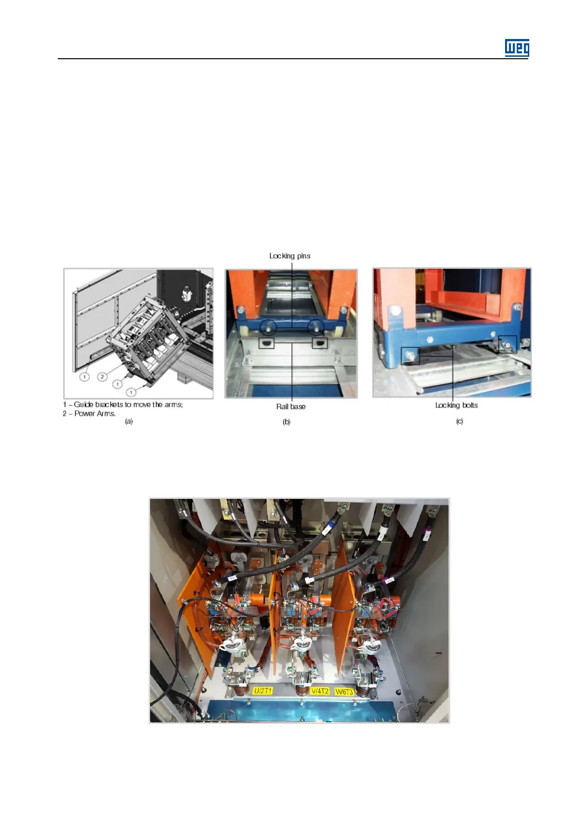
1. Use the auxiliary guide brackets, shown in figure 5.17 (a), to move the arms. These auxiliary guide brackets
are supplied with the product and are positioned at the internal part of the medium voltage compartment door
when they are not used.
2. The arm must be inserted until the locking pins, located at the rear of the arm, fit into the rail base, refer to
figure 5.17 (b).
3. 3. Install the locking bolts at the arm front bottom part, refer to figure 5.17 (c).
Figure 5.17 (a) to (c): Details of the arm insertion stages
For the SSW7000C, the power arms are lighter and are fixed at the panel rear by means of screws, as shown
in figure 5.18.
Figure 5.18 SSW7000C Power arms installation.