SSW7000 | 5-30
Installation and Connection
5.2.10. User Signal and Control Connections
The signal connections (analog inputs and outputs) and control (digital inputs and outputs) available to the user
are performed in the control board 1 (CC11).
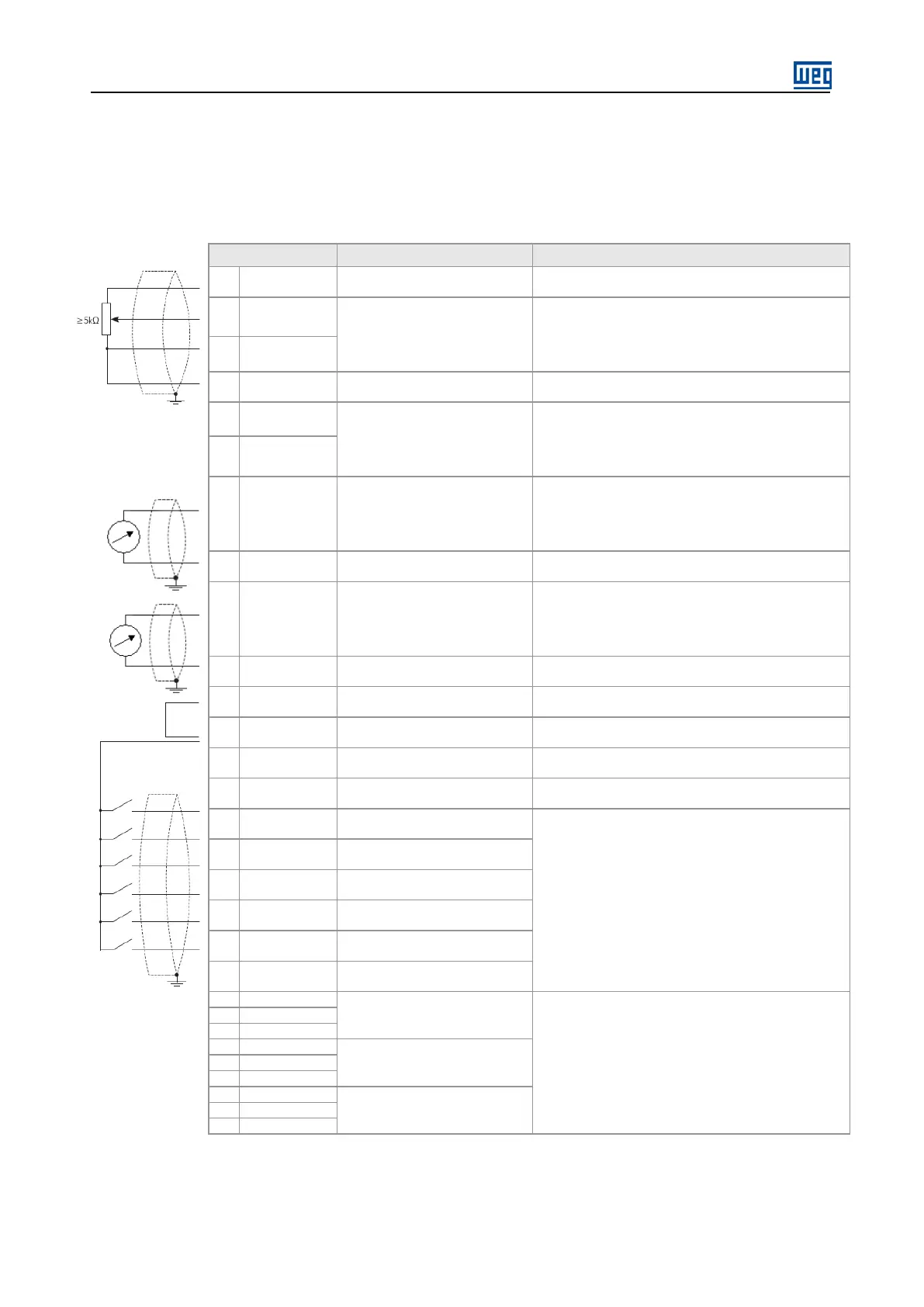
Figure 5.34: XC1 terminal strip description
1 +REF Potentiometer positive referente
Output voltage:+5.4 V, ±5 %.
Maximum output current: 2 mA
2 AI1+
Analog Input 1:
No function
Resolution: 12 bits
Signal: 0 to 10 V (R
IN = 400kΩ)
Signal: 0 to 20mA or 4toa 20mA (R
IN = 500Ω)
3 AI1-
4 REF Potentiometer negative reference
Output voltage: -4.7 V, ±5 %.
Maximum output current: 2 mA
5 AI2+
Analog Input 2:
No function
Resolution: 11 bits + signal
Signal: 0 to 10 V (R
IN = 400kΩ)
Signal: 0 to 20mA or 4 to 20mA (R
IN = 500Ω)
6 AI2-
7 AO1
Analog output 1:
No function
Resolution: 11 bits
Signal: 0 to 10 V (R
L ≥10kΩ)
Signal: 0 to 20mA or 4 to 20mA (R
L ≤ 500Ω)
Protected against short circuit
8 AGND (24 V) Reference (0 V) for analog ouputs
Connected to the ground (frame) throught impedance:
940 Ω resistor in parallel with a 22 nF capacitor
9 AO2
Analog output 2:
No function
Resolution: 11 bits
Signal: 0 to 10 V (R
L ≥10kΩ)
Signal: 0 to 20mA or 4 to 20mA (R
L ≤ 500Ω)
Protected against short circuit
10 AGND (24 V)
Reference (0 V) for the analog
outputs
Connected to the ground (frame) throught impedance:
940 Ω resistor in parallel with a 22 nF capacitor
11 DGND*
Reference (0 V) for the 24 Vdc
power supply
Connected to the ground (frame) throught impedance:
940 Ω resistor in parallel with a 22 nF capacitor
12 COM
Common point of the digital
Inputs
13 24 Vcc 24 Vdc power supply
24 Vdc, ±8 % power supply
Capacitor: 500 mA
14 COM
Common point of the digital
Inputs
15 DI1
Digital Input 1:
Start / Stop
6 Isolated digital Inputs
High level ≥ 18 V
Low level ≤ 3 V
Maximum input voltage. = 30 V
Input current: 11 mA @ 24 Vcc
16 DI2
17 DI3
Digital Input 3:
No function
18 DI4
Digital Input 4:
No function
19 DI5
Digital Input 5:
No function
20 DI6
Digital Input 6:
No function
Digital output 1 DO1
Running
Contact rating:
Maximum voltage: 240 Vcac
Maximum current: 1 A
NF – Normally closed contact
C - Common
NA – Normally open contact
Digital output 2 DO2
Bypass
Digital output 3 DO3
Fault