SSW7000 | 10-4
Troubleshooting and Maintenance
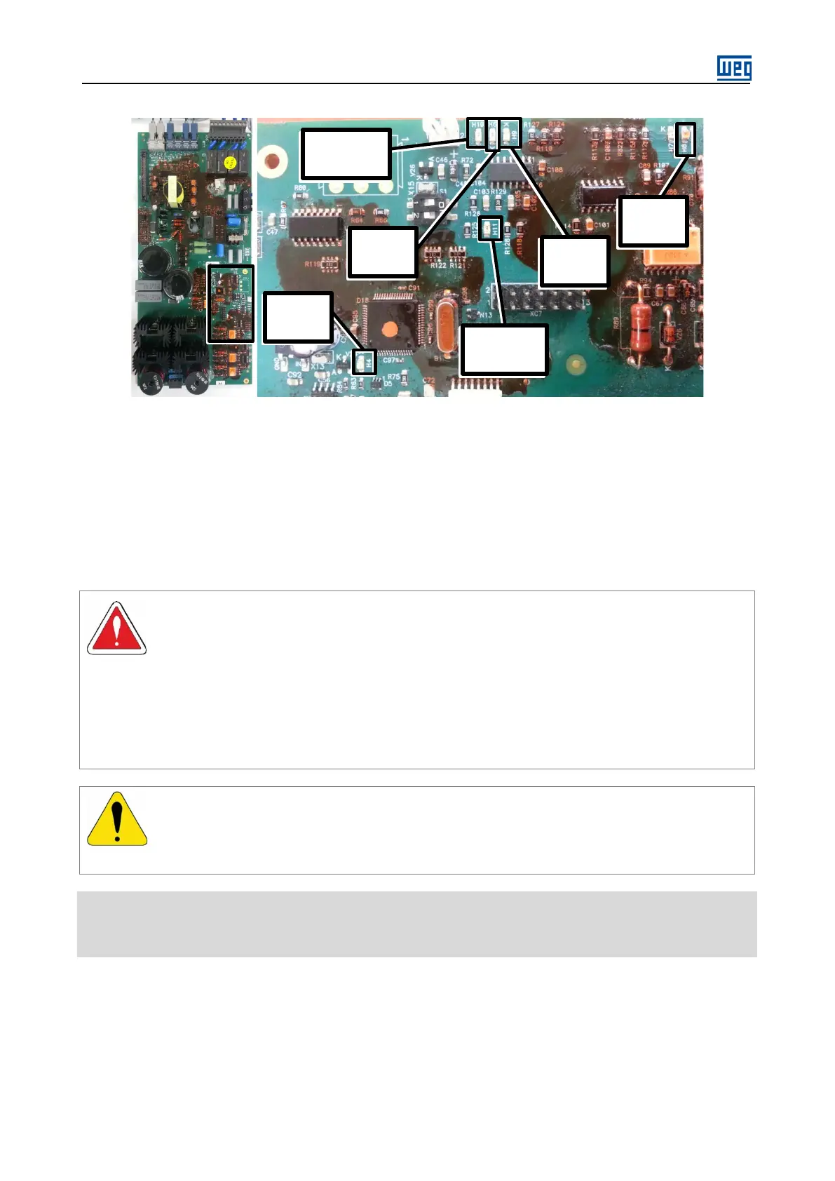
Figure 10.1: Location of the fault LEDs of the FSMT board.
Dip Switch 1: Defines the maximum output voltage of the FSMT board (connector XC2). If open (default option),
the output voltage will be 83 Vac (FSMT.00) and 66 Vac (FSMT.01). If closed, it will be 87 Vac (FSMT.00) and 69
Vac (FSMT.00).
Dip Switch 2: Enables protection against power supply undervoltage of the FSMT board during the motor start.
The reset limit is 121.5Vdc (90 Vac).
10.4. PREVENTIVE MAINTENANCE
Always disconnect the input power before touching any electrical component associated to the
SSW7000. Follow the disconnection sequence described in this manual, item 10.4.1 - SSW7000
Disconnection Sequence.
High voltages may be present even after disconnecting the power supply.
Wait at least 3 minutes for the complete discharge of the power capacitors.
Always connect the equipment frame to the protective earth (PE) at the suitable connection point.
ATTENTION!
Electronic boards have components sensitive to electrostatic discharges.
Do not touch directly on components or connectors. If necessary, touch the grounded metallic
frame before or use an adequate grounded wrist strap.
Do not perform any high pot tests with the SSW7000!
If it is necessary, consult WEG.