SSW7000 | 3-5
Figure 3.5: Ground fault detection by current.
3.1.13. Command for Power Factor Correction
NOTE!
The capacitor bank for power factor correction is provided in an additional column coupled to
the SSW7000
Power factor correction capacitors must never be installed at the SSW7000 output
(U / 2T1, V / 4T2 and W / 6T3).
NOTE!
The current carrying capacity of digital outputs DO1, DO2 and DO3 is 1A, as described in 9.2
Control for a SSW7000
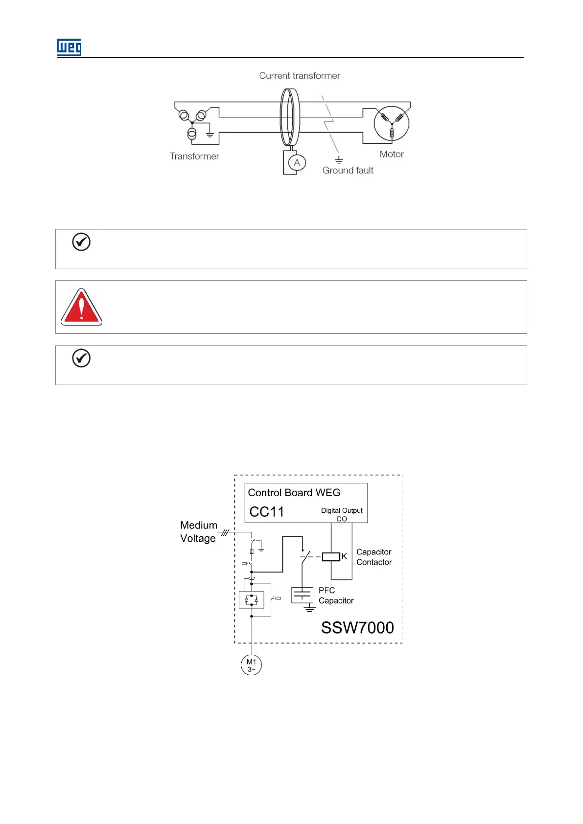
The SSW7000 can control the motor power factor correction (PFC) capacitor bank directly through a digital output
(DO1, DO2 or DO3) programmed for “PFC Control”. The digital output will then be activated after the motor starts
and after the bypass contactor closes, thus preventing the capacitor bank from being activated with the motor
turned off or during the motor start or stop.
Figure 3.6: Connection to PFC Control for a SSW7000C