SSW7000 | 6-4
6.1.4. FSMT Board Connections
Table 6.6: Description of the FSMT board connectors
X1 AC supply
- 110 to 230 Vac (-15 % ( 93,5 Vac ) to 10 % ( 253 Vac ) ) or 125 to 320 Vdc
Control Unit Version 3:
- 100 to 230 Vac (-15 % ( 85 Vac ) to 10 % ( 253 Vac ) ) or 110 to 320 Vdc
3 Ground
X8 Command ouput for the contactors
AC – Coil – Bypass contactor
Supply for the contactors
AC – Coil – Line contactor
Supply for the contactors
AC – Coil – Rotation direction
6 Phase Supply for the contactors
Connections between boards
Connections between boards
Communication between the C1 and C2 control boards through optic cables
Current and voltage synchronism feedback
Connections between FSMT and CSM transformer
Phase – transformer TF primary - CSM
Phase – transformer TF primary - CSM
NOTE!
The timer delay must be set for 0.2 seconds.
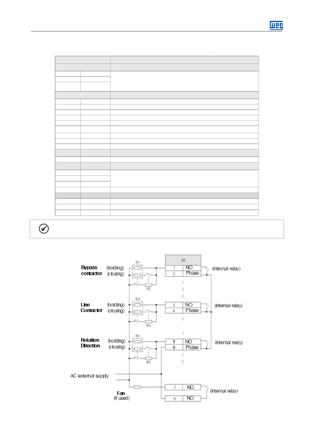
Connection diagram of the digital outputs with defined functions to control contactors with AC coil and auxiliary
closing coil.
Figure 6.2: FSMT AC contactor wiring diagram.

 Loading...