SSW7000 | 5-15
Installation and Connection
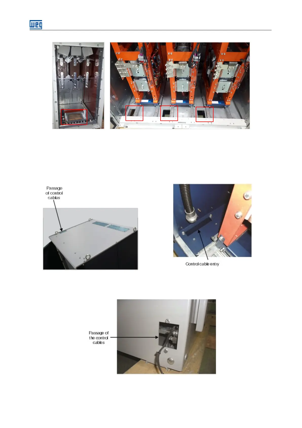
a): Power cable entry (b): Power cable outlet
Figure 5.14 (a) e (b): Passage of the power cables – SSW7000D - IP41.
5.1.11. Control Cable Entry
The passage of the control cables (digital and analog inputs and outputs, thermistor PT100 and low voltage supply
cables) in the panels IP41 and Nema 12 of the SSW7000 is shown in figure 5.15 and figure 5.16 respectively.
(a) Passage of cables by the upper part of the panel
(b) Passage of the cables by the lower part of the panel
Figure
5.15: (a) e (b): Passage of the control cables – IP41.
Figure 5.16:
Passage of the control cables by the lower part of the left side of the panel – Nema 12.