SSW7000 | 5-17
Installation and Connection
5.2. ELECTRICAL INSTALLATION
D
Before beginning the connections, make sure the power supply is disconnected.
!
The SSW7000 cannot be used as an emergency stop
mechanism.
ATTENTION!
The following information is intended to be a guide for a proper installation. You must also comply
with applicable local regulations for electrical installations.
ATTENTION!
During the commissioning, apply power first to the electronics and program the minimum necessary
parameters to be able to run the Test Mode (according to the programming manual, section 14.2 -
Test Mode).
The Test Mode execution is essential for the confirmation of the correct operation of the SSW7000
panel main components.
Start the motor only if the Test Mode results were satisfactory.
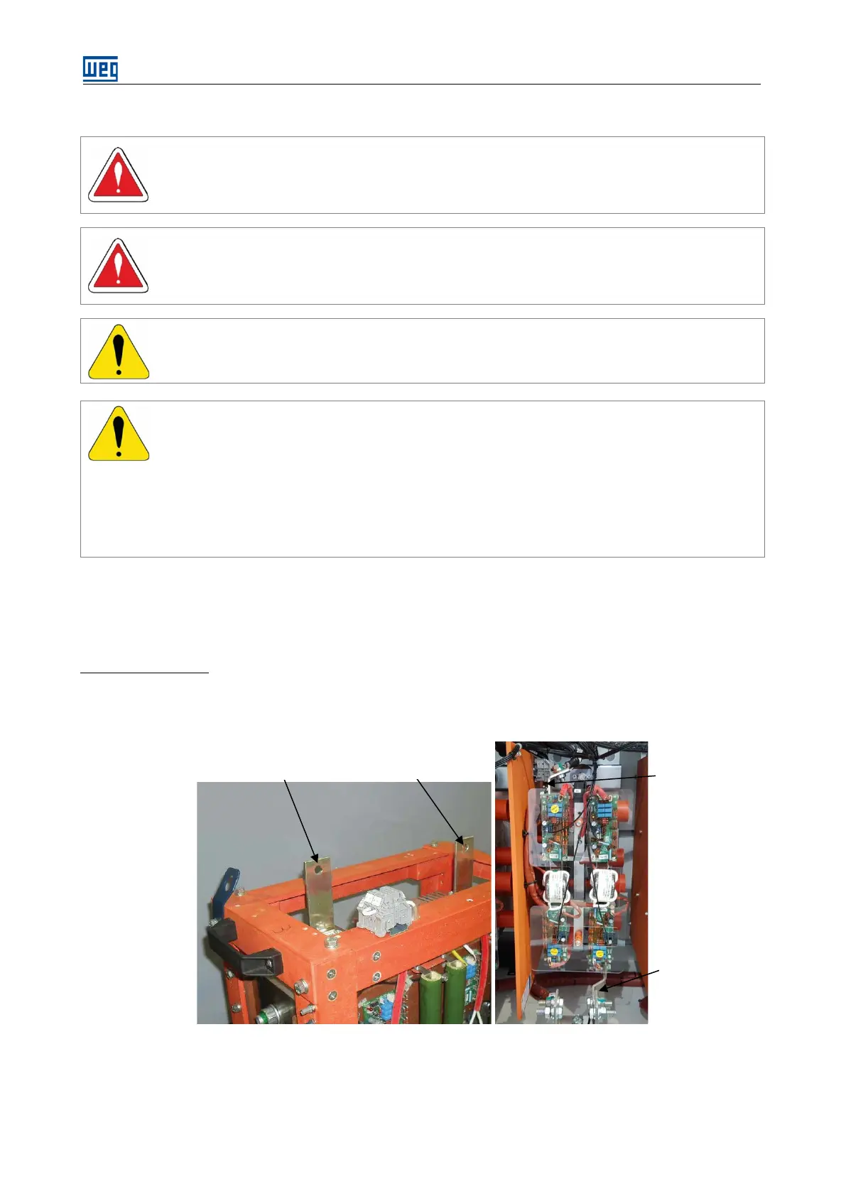
5.2.1. Power Arm Electrical and Fiber Optic Connections
After inserting the power arms (R-U, S-V and T-W phases) connect them to the power cables, to the fiber optic
cables and to the firing board power supply. All the power arm connections are easy to access.
Power connections:
The input and output power connections are made with cables with lugs, connected to the module copper
terminals. For SSW7000C, the input connection is at the top of the module and is made using cables with lugs.
The output connection is made using copper bars.
SSW7000 SSW7000C
Figure 5.19: Connection of the power cables to the power arms