SSW7000 | 5-31
Installation and Connection
Note: in order to check the accessories available for each slot, refer to table 8.1.
Figure 5.35: Disposition of the connections on the control board 1
Directions for signal and control wiring:
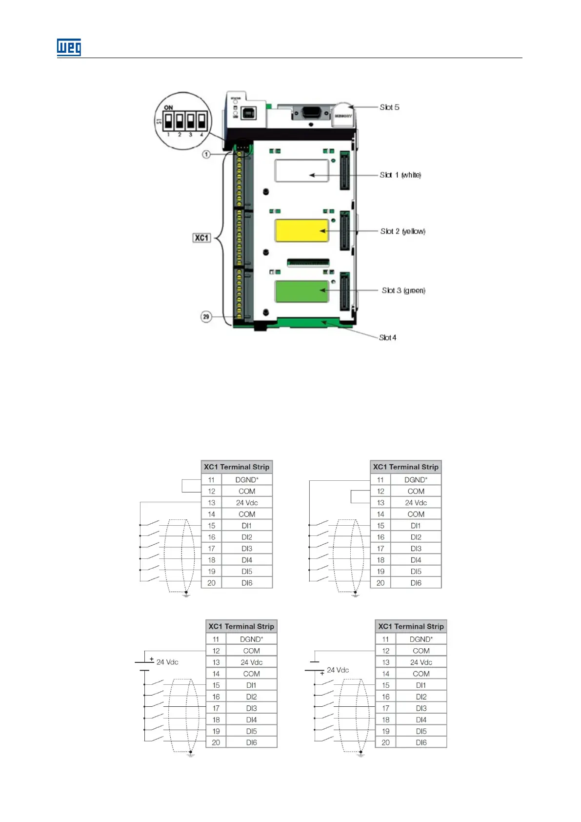
The SSW7000 digital inputs allow several types of electrical connection. They can be activated by the internal
auxiliary +24 Vdc supply using as the common point the DGND* or the +24 Vdc. They can also be activated
through an external +24 Vdc (wired to a PLC) using either the 0 V of that power supply or the +24 Vdc as the
common point, according to the application needs:
Figure 5.36: Wiring diagram of the digital inputs using the internal power supply
Figure 5.37:
Wiring diagram of the digital inputs using na external power supply