12 2576780000/00/02-2018
Installation
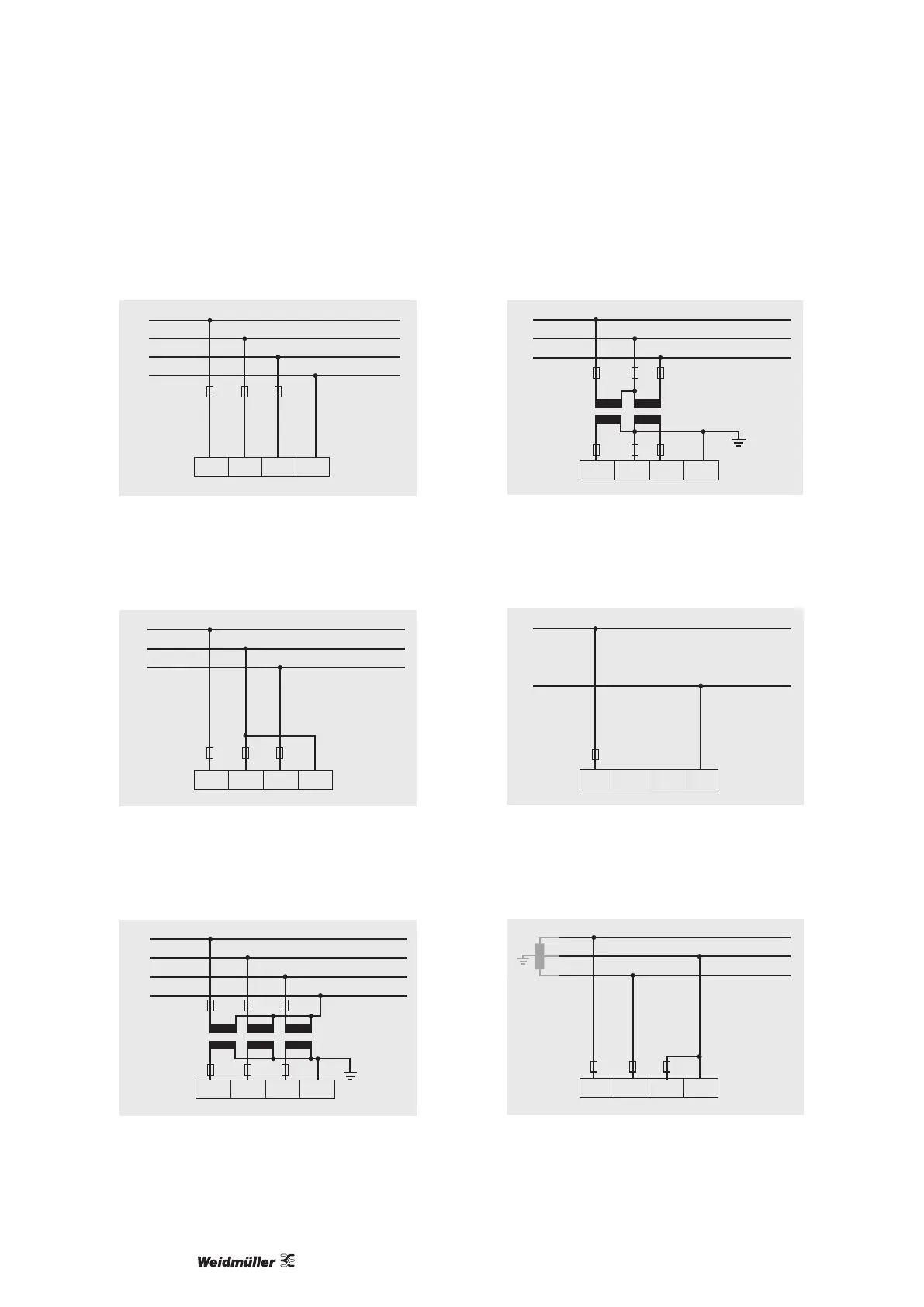
Connection diagram, voltage measurement
• 3p 4w (addr. 509= 0), factory setting
L1
L2
L3
N
V1 V2 V3 VN
Fig.: System with three-phase conductors and a neutral conduc-
tor.
• 3p 4u (addr. 509 = 2)
L1
L2
L3
V1 V2 V3 VN
Fig.: System with three-phase conductors and no neutral conduc-
tor. Measured values that require a neutral refer to a calcu-
lated neutral.
• 3p 4wu (addr. 509 = 1)
L1
L2
L3
N
V1 V2 V3 VN
Fig.: System with three-phase conductors and a neutral conduc-
tor. Measurement via voltage transformer.
• 3p 2u (addr. 509 = 5)
L1
L2
L3
V1 V2 V3 VN
Fig.: System with three-phase conductors and no neutral conduc-
tor. Measurement via voltage transformer. Measured values
that require a neutral refer to a calculated neutral.
• 1p 2w1 (addr. 509 = 4)
L1
N
V1 V2 V3 VN
Fig.: Measured values derived from the V2 and V3 voltage meas-
urement inputs are assumed to be zero and not calculated.
• 1p 2w (addr. 509 = 6)
L1
L2
V1 V2 V3 VN
Fig.: TN-C system with single-phase, three-wire connection.
Measured values derived from the V3 voltage measurement
input Zero are assumed to be zero and not calculated.