92576780000/00/02-2018
Installation
Mounting
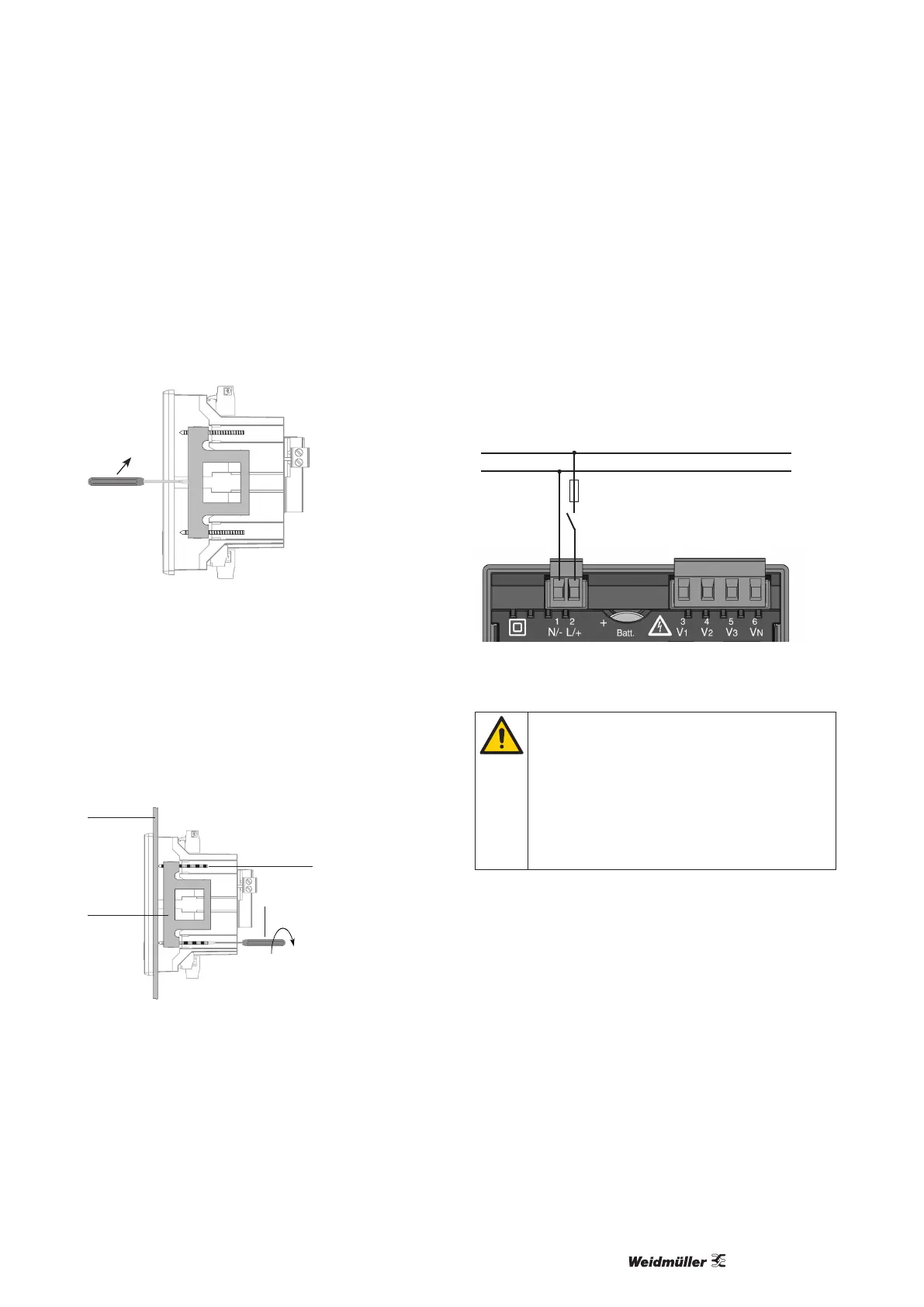
The Energy Meter 610/610-PB is xed using the mounting clips
found on the side of the switch panel. Before inserting the device,
they should be moved out of the way in a horizontal lever using a
screwdriver, for example.
Fig.: Side view Energy Meter 610/610-PB with mounting clips.
Loosening the clips is done using a screwdriver and a hori-
zontal lever effect.
The fastening is then done when the device is pushed in an the
clamps lock in place when the screws are tightened.
• Please tight the xing screws until they contact the mounting
plate easily.
• Tighten with two further turns, the clamping screws (are the
screws tightened too much, the mounting bracket will be de-
stroyed)
Mounting plate
Fixing screw
Screwdriver
Mounting
clips
Contacting of the xing
screws to the mounting
plate: Tighten with
maximum two further
turns for the installation
Installation
Supply voltage
A supply voltage is required to operate the Energy
Meter 610/610-PB. The voltage supply is connected via plug-in
terminals on the back of the device.
Before applying the supply voltage, ensure that the voltage and
frequency correspond with the details on the nameplate!
Separator
Fuse
N
L
Fig.: Connection example of the supply voltage to the Energy
Meter 610/610-PB
• The supply voltage must be connected through a fuse
according to the technical data.
• In building installations, the supply voltage must be pro-
vided with a disconnect switch or circuit breaker.
• The disconnect switch must be attached near the de-
vice and must be easily accessible by the user.
• The switch must be labelled as a separator for this de-
vice.
• Voltages that exceed the permissible voltage range can
destroy the device.