212576780000/00/02-2018
Installation
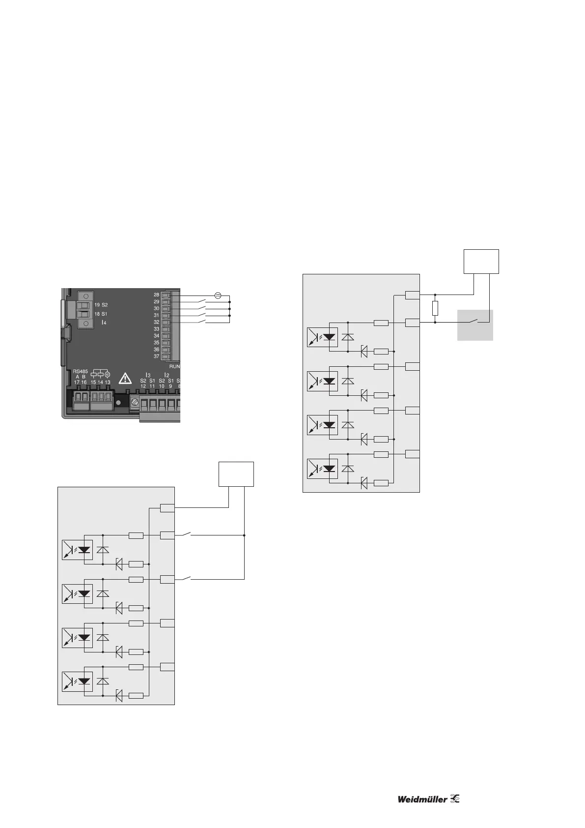
Digital inputs
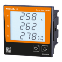
The Energy Meter 610-PB and Energy Meter 610 have 4 digital
inputs, each of which can have a signal transducer connected.
On a digital input an input signal is detected if a voltage of at least
10 V and maximum 28 V is applied and where a current of at least
1 mA and maximum 6 mA ows at the same time. Wiring longer
than 30 m must be screened.
Note the correct polarity of the supply voltage!
-
+
Fig.: Connection example for digital inputs.
-
+
24V DC
S1
S2
External
auxiliary voltage
28
29
30
31
32
2k21
2k21
2k21
2k21
2k21
2k21
2k21
2k21
Digital
Input 1
Digital
Input 2
Digital
Input 3
Digital
Input 4
Energy Meter 610/610-PB
Digital inputs 1-4
Fig.: Example for the connection of external switch contacts S1
and S2 to digital inputs 1 and 2.
S0 pulse input
You can connect an S0 pulse transducer per DIN EN 62053-31 to
any digital input.
This requires an auxiliary voltage with an output voltage in the
range 20 to 28 V DC and a resistor of 1.5 kOhm.
28
29
30
31
32
2k21
2k21
2k21
2k21
2k21
2k21
2k21
2k21
Digital
Input 1
Digital
Input 2
Digital
Input 3
Digital
Input 4
Energy Meter 610/610-PB
Digital inputs 1-4
-
+
24V DC
External
auxiliary voltage
S0 pulse
transducer
1.5k
Fig.: Example for the connection of an S0 pulse transducer to
digital input 1.