8 2576780000/00/02-2018
Assembly
Connection variants
Connecting a Energy Meter 610 or 610-PB to a PC via the USB
interface:
PC
ecoExplorer go
RS232
RS485
Energy
Meter
610/610-PB
PC
ecoExplorer go
PC
ecoExplorer go
Energy
Meter
610/610-PB
Energy
Meter
610/610-PB
Energy
Meter
610/610-PB
Energy
Meter
610/610-PB
USB (Type A) USB (Type B)
Connecting a Energy Meter 610 or 610-PB to a PC via an interface
converter:
PC
ecoExplorer go
RS232
RS485
Energy
Meter
610/610-PB
PC
ecoExplorer go
PC
ecoExplorer go
Energy
Meter
610/610-PB
Energy
Meter
610/610-PB
Energy
Meter
610/610-PB
Energy
Meter
610/610-PB
Energy
Analyser
D550
RS232 RS485
RS485
Connecting a Energy Meter 610 or 610-PB via a Energy
Analyser D550 as gateway:
PC
ecoExplorer go
RS232
RS485
Energy
Meter
610/610-PB
PC
ecoExplorer go
PC
ecoExplorer go
Energy
Meter
610/610-PB
Energy
Meter
610/610-PB
Energy
Meter
610/610-PB
Energy
Analyser
D550
Ethernet RS485
RS485
Assembly
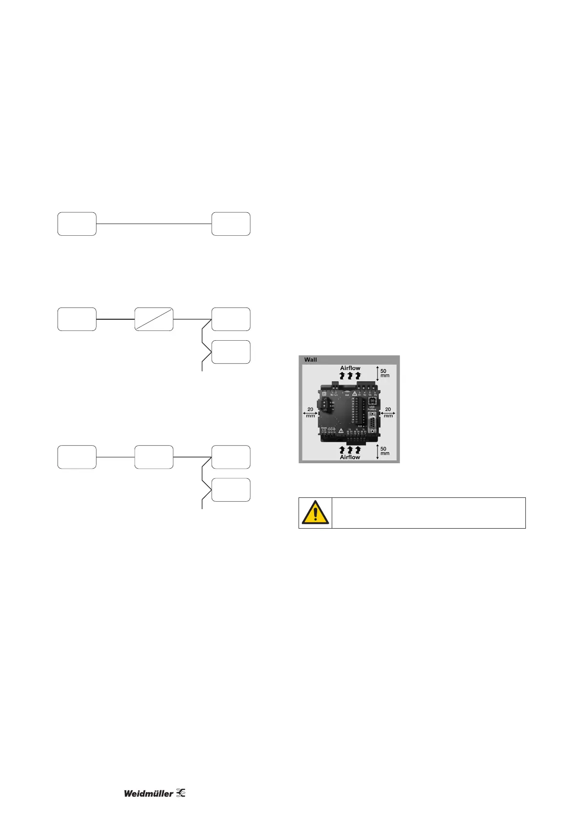
Installation location
The Energy Meter 610/610-PB is suitable for installation in perma-
nent, weatherproof switchboards. Conducting switchboards must
be earthed.
Installation position
The Energy Meter 610/610-PB must be installed vertically in order
to achieve sufcient ventilation. The clearance to the top and bot-
tom must be at least 50 mm and 20 mm at the sides.
Front panel cutout
Cutout dimensions:
92
+0,8
x 92
+0,8
mm.
Fig.: Energy Meter 610/610-PB installation location (rear view)
Failure to comply with the minimum spacing can de-
stroy the Energy Meter 610/610-PB at high ambient
temperatures!