192576780000/00/02-2018
Installation
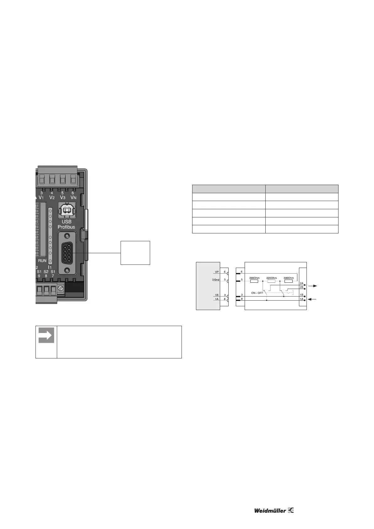
Probus interface (only Energy Meter 610-PB)
This 9-pin D-sub receptacle RS485 interface supports the Probus
DP V0 slave protocol.
For the simple connection of inbound and outbound bus wiring
these should be connected to the Energy Meter 610-PB via a
Probus connector.
D-sub
receptacle
for Probus
Fig.: Energy Meter 610-PB with D-sub receptacle for Probus
(View on rear).
The device address can be congured by using the pa-
rameter 000 if the device is used in a Probus-System.
The baud rate in a Probus system is detected auto-
matically and must NOT be set via the address 001!
Connection of the bus wiring
The inbound bus wiring is connected to terminals 1A and 1B of the
Probus connector. The continuing bus wiring for the next device
in line should be connected to terminals 2A and 2B.
If there are no subsequent devices in the line then the bus wiring
must be terminated with a resistor (switch to ON).
With the switch set to ON terminals 2A and 2B are switched off for
further continuing bus wiring.
Transfer speeds in Kbit/s max. segment length
9.6 / 19.2 / 45.45 / 93.75 1200 m
187.5 1000 m
500 400 m
1500 200 m
3000 / 6000 / 12000 100 m
Tab.: Segment lengths per Probus specication.
Profibus connector (external)
Termination resistors
Screw terminal
Other
Profibus-
Subscribers
D-sub
9-pole,
connector
D-sub
9-pole,
connector
Energy Meter
610-PB
Profibus
Fig.: Probus connector with termination resistors.