18 2576780000/00/02-2018
Installation
Bus structure
• All devices are connected in a bus structure (line) and each de-
vice has its own address within the bus (also see programming
parameters).
• Up to 32 stations can be interconnected in one segment.
• The cable is terminated with resistors (bus termination, 120 ohm
1/4 W) at the beginning and end of a segment.
• If there are more than 32 stations, repeaters (line ampliers)
must be used in order to connect the individual segments.
• Devices with activated bus termination must be supplied with
power.
• It is recommended to set the master at the end of a segment.
• The bus is inoperative if the master is replaced with an activated
bus termination.
• The bus can become unstable if the slave is replaced with an
activated bus termination or is dead.
• Devices that are not involved in the bus termination can be ex-
changed without making the bus unstable.
• The shield has to be installed continuously and needs to be
broadly and well conducting connected to an external low volt-
age (or potential) ground at the end.
SlaveSlaveSlave
Slave Slave Slave Repeater
Slave Slave Slave Slave
Master
Speisung notwendig / power supply
necessary
Busabschluß eingeschaltet / bus
terminator on
T
T
T
T
T
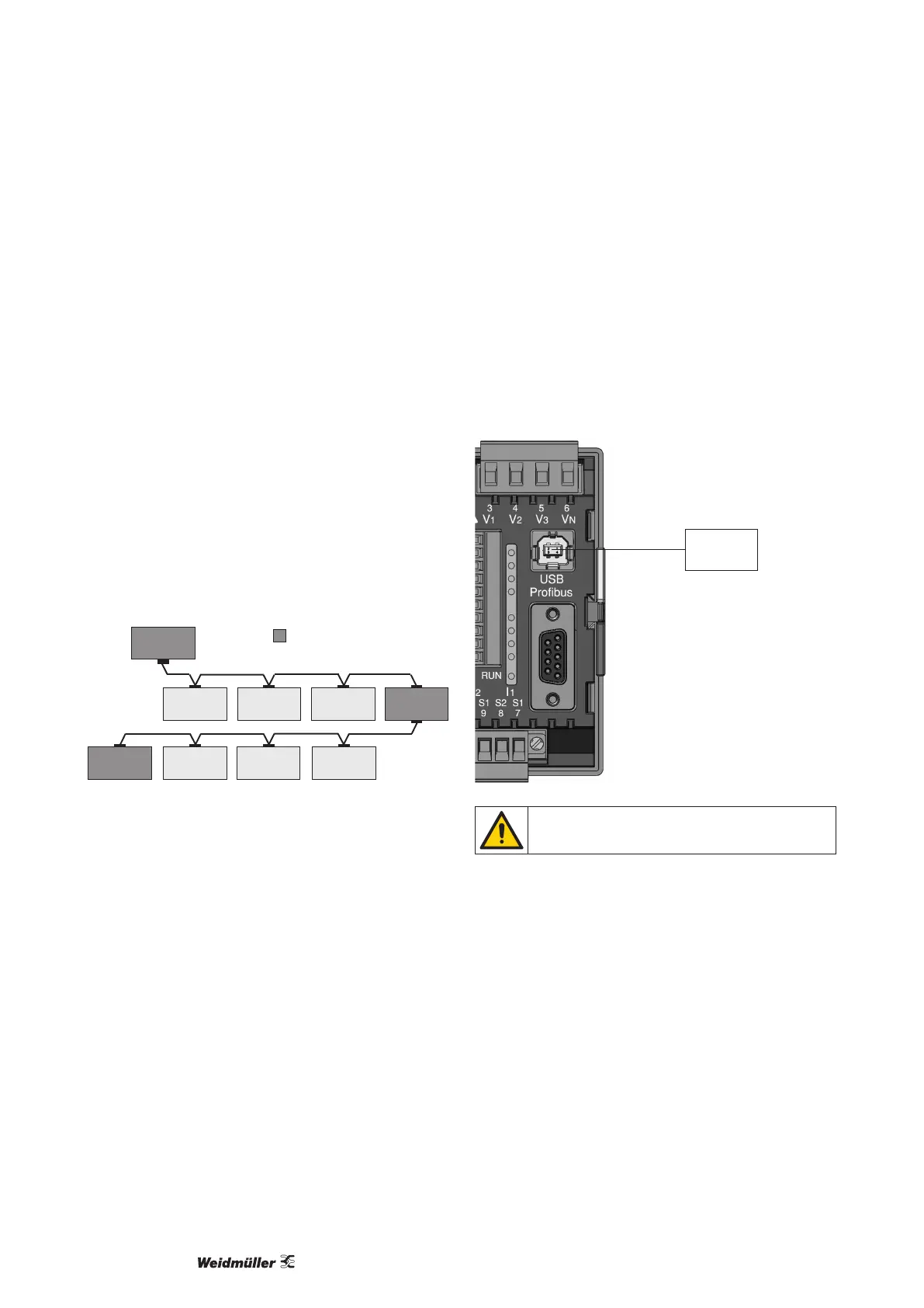
Fig.: Diagram of bus structure
USB interface
The Universal Serial Bus (USB) enables a rapid and uncompli-
cated connection between the device and a computer. After the in-
stallation of the USB driver the device data can be read out via the
ecoExplorer go software and rmware updates can be installed.
The USB2.0 connection cable with A/B connectors included in the
scope of deliverables is required for the USB connection of the
device to the USB interface of the computer.
USB A/B
PC
The cable length of the USB connection should not
exceed 5 m.