172576780000/00/02-2018
Installation
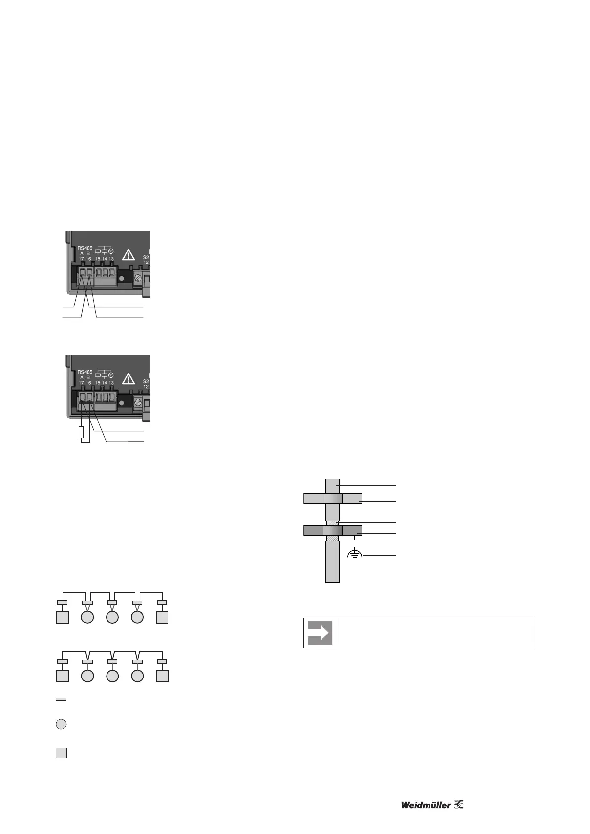
RS485 interface
The RS485 interface is designed with the Energy Meter 610/610-PB
as a 2-pole plug contact and communicates via the Modbus RTU
protocol (also see programming parameters).
A
B
RS485 bus
Fig.: RS485 interface, 2-pole plug contact
A
B
120 Ω
RS485 bus
Fig.: RS485 interface, 2-pole plug contact with terminating resis-
tor
Terminating resistors
The cable is terminated with resistors (120 ohm 1/4 W) at the be-
ginning and end of a segment.
The Energy Meter 610/610-PB has no terminating resistors.
Correct
Incorrect
Terminal block in the switch cabinet.
Device with RS485 interface.
(without a terminating resistor)
Device with RS485 interface.
(with terminating resistor on the device)
Shielding
A twisted and shielded cable must be provided for connections via
the RS485 interface.
• Ground the shields of all cables that run into the cabinet at the
cabinet entry.
• Connect the shield so it has a large contact area and conduc-
tively with a low-noise earth.
• Mechanically trap the cable above the earthing clamp in order to
avoid damage from cable movement.
• Use the appropriate cable inlets, e.g. PG screw joints, to insert
the cable into the switch cabinet.
Cable type
The cable used must be suitable for an ambient temperature of at
least 80 °C.
Recommended cable types:
Unitronic Li2YCY(TP) 2x2x0.22 (Lapp cable)
Unitronic BUS L2/FIP 1x2x0.64 (Lapp cable)
Maximum cable length
1200 m with a baud rate of 38.4 k.
Cable
Strain relief
Mesh wire shielding of the cable
Earthing clamp
Low-noise earth
Fig.: Shielding design for cabinet entry.
For the wiring of the Modbus connection, CAT cables
are not suitable. Please use the recommended cables.