16 2576780000/00/02-2018
Installation
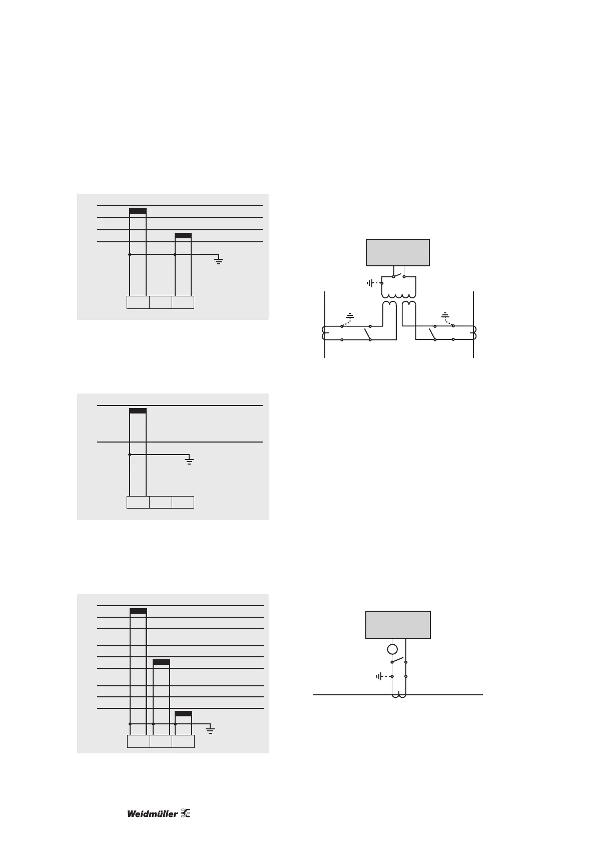
• 2p 4w (addr. 510 = 5)
L1
L2
L3
N
I1 I2 I3
Fig.: System with uniform phase loading. The measured values
for the I2 current measurement input are calculated.
• 1p 2w (addr. 510 = 7)
L1
N
I1 I2 I3
Fig.: Measured values derived from the I2 and I3 current meas-
urement inputs are assumed to be zero and not calculated.
• 3p 1w (addr. 510 = 8)
L1
L2
L3
I1 I2 I3
L1
L2
L3
L1
L2
L3
Fig.: Three systems with uniform phase loading. The current
measurement values of the phases of the respective system
where are no CTs connected are calculated (I2/I3 resp. I1/I3
resp. I1/I2).
Total current measurement
If the current measurement takes place via two current transform-
ers, the total transformer ratio of the current transformer must be
programmed in the Energy Meter 610/610-PB.
Energy Meter
S2
I
S
1
P1
P2
Einspeisung 1
Supply 1
Einspeisung 2
Supply 2
1P1
1P2
(K)
(L)
(k)
(l)
1S
2
1S1
1S1 1S2 2S1 2S2
2S1
2S2
(k)
(l)
(K)
(L)
2P
1
2P2
Verbraucher A
Consumer A
Verbraucher B
Consumer B
Fig.: Current measurement via a total current transformer (exam-
ple).
Example:
The current measurement takes place via two current trans-
formers. Both current transformers have a transformer ratio of
1000/5 A. The total measurement is performed with a 5+5/5 A total
current transformer.
The Energy Meter 610/610-PB must then be set as follows:
Primary current: 1.000 A + 1.000 A = 2.000 A
Secondary current: 5 A
Ammeter
If you want to measure the current not only with the Energy
Meter 610/610-PB but also with the ammeter, the ammeter must
be connected in series with the Energy Meter 610/610-PB.
Energy Meter
S2
I
S
1
Einspeisung
Supply
Verbraucher
Consumer
A
(k)S
1 S2(l)
P
2(L)(K)P1
Fig.: Current measurement with an additional ammeter (exam-
ple).