152576780000/00/02-2018
Installation
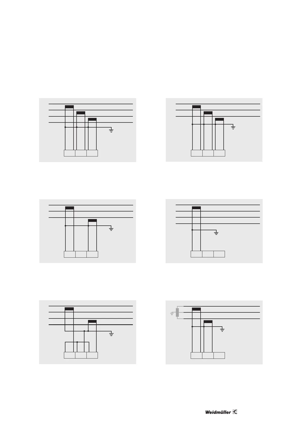
Connection diagram, current measurement
• 3p 4w (addr. 510= 0), factory setting
L1
L2
L3
N
I1 I2 I3
Fig.: Measurement in a three-phase net-work with an unbalanced
load.
• 3p 2i0 (addr. 510 = 2)
L1
L2
L3
I1 I2 I3
Fig.: The measured values for the I2 current measurementinput
are calculated.
• 3p 2i (addr. 510 = 1)
L1
L2
L3
N
I1 I2 I3
Fig.: System with uniform phase loading. The measured values
for the I2 current measurement input are measured.
• 3p 3w3 (addr. 510 = 3)
L1
L2
L3
I1 I2 I3
Fig.: Measurement in a three-phase net-work with an unbalanced
load.
• 3p 3w (addr. 510 = 4)
L1
L2
L3
N
I1 I2 I3
Fig.: System with uniform phase loading. The measured values
for the I2 and I3 current measurement inputs are calculated.
• 1p 2i (addr. 510 = 6)
I1 I2 I3
L1
L2
Fig.: Measured values derived from the I3 current measurement
input are assumed to be zero and not calculated.