20 2576780000/00/02-2018
Installation
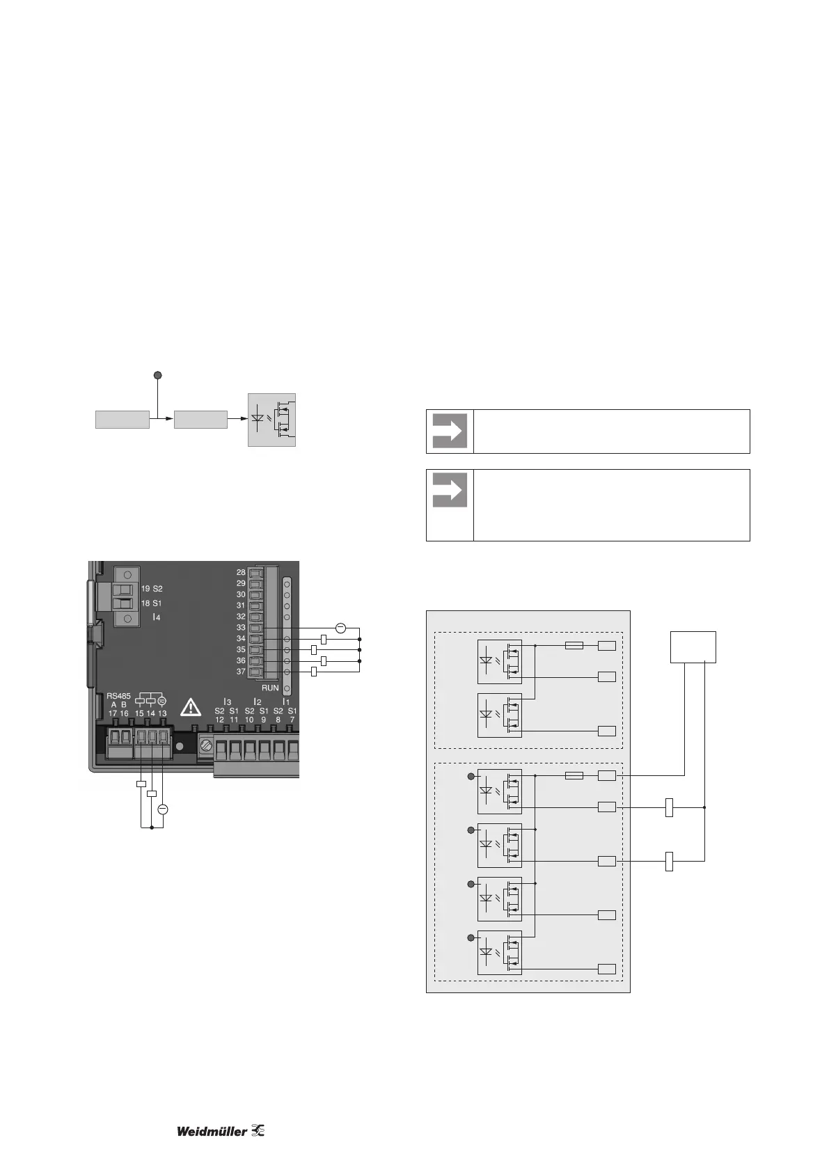
Digital outputs
The Energy Meter 610 and Energy Meter 610-PB have 6 digital
outputs, whereby these are split into two groups of 2 and 4 outputs.
Digital outputs, Group 1
• The status indicator appears on the display at K1 or K2
• The status indicator on the display is not dependent on an inver-
sion being activated (NC / NO)
Digital
output 1
e.g.
Comparator group
K1/K2 display
status indicator
InverterSource
Digital outputs, Group 2
• The status of the inputs and outputs in Group 2 is indicated by
the associated LED (cf. chapter LED status bar).
~
~
Group 2
Group 1
Fig.: Connection digital/pulse outputs
These outputs are electrically isolated from the evaluation elec-
tronics by optocouplers. The digital outputs have a common refer-
ence.
• The digital outputs can switch DC and AC loads.
• The digital outputs are not short circuit protected.
• Connected cables longer than 30 m must be shielded.
• An external auxiliary voltage is required.
• The digital outputs can be used as pulse outputs.
• The digital outputs can be controlled via the Modbus.
• The digital outputs can output results from comparators
When using the digital outputs as pulse outputs the
auxiliary voltage (DC) must have a max. residual rip-
ple of 5 %.
Functions for the digital outputs can be adjusted clearly
in the ecoExplorer go software. A connection between
the Energy Meter 610/610-PB and the PC via an in-
terface is required for the use of the ecoExplorer go
software.
DC connection example
K4
External
auxiliary voltage
+
24V DC
-
K3
DC
DC
33
34
35
36
37
Digital Ouput 3
Digital Ouput 4
Digital Ouput 5
Digital Ouput 6
13
14
15
Digital Ouput 1
Digital Ouput 2
Energy
Meter 610/610-PB
Group 1: Group 2:
LEDLEDLEDLED
Fig.: Example for two relays connected to the digital outputs