132576780000/00/02-2018
Installation
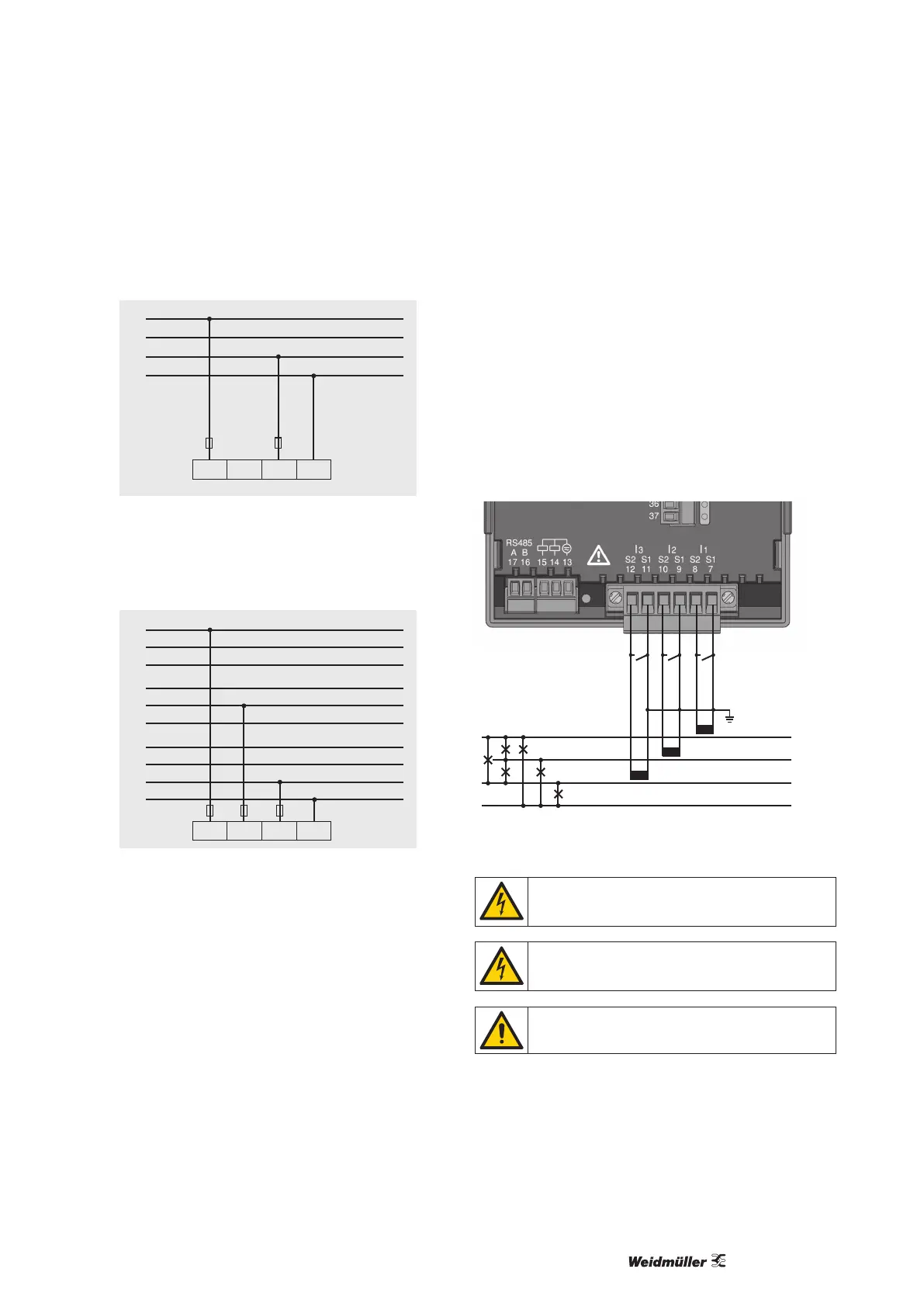
• 2p 4w (addr. 509 = 3)
L1
L2
L3
N
V1 V2 V3 VN
Fig.: System with uniform phase loading. The measured values
for the V2 voltage measurement input are calculated.
• 3p 1w (addr. 509 = 7)
L1
L2
L3
L1
L2
L3
L1
L2
L3
V1 V2 V3 VN
N
Fig.: Three systems with uniform phase loading. The measure-
ment values L2/L3 resp. L1/L3 resp.L1/L2 of the respective
system are calculated.
Current measurement via I1 to I4
The Energy Meter 610/610-PB is designed to have current trans-
formers with secondary currents from ../1A and ../5A attached cia
terminals I1-I4. The factory default for the current transformer ratio
is 5/5A and must be adapted to the current transformer employed
if necessary.
Direct measurement without a current transformer is not possible
using the Energy Meter 610/610-PB.
Only AC currents can be measured - DC currents cannot.
Via the current measurement input I4 only an apparent current
measurement is carried out thanks to the lack of a multiplier. Pow-
er measurements are therefore not possible using the I4 input.
L2
L3
N
L1
Load
Fig.: Current measurement (I1-I3) via current transformers (con-
nection example)
Caution!
The test leads must be designed for an operating tem-
perature of at least 80 °C.
Caution!
The current measurement inputs are dangerous to
touch.
The attached screw terminal has to be xed sufciently
with two screws on the device!