48 2576780000/00/02-2018
Error messages
Warnings
Warnings are less serious errors and can be acknowledged with
buttons 1 or 2. The measured values continue to be recorded and
displayed. This error is re-displayed after each voltage recovery.
Error Description of the error
EEE
500
The mains frequency could not be determined.
Possible causes:
The voltage at L1 is too small.
The mains frequency does not range between 45
and 65 Hz.
Remedy:
Check the mains frequency.
Select xed frequency on the device.
Serious errors
The device must be sent to the manufacturer for inspection.
Error Description of the error
EEE
910
Error when reading the calibration.
Internal causes of the error
The Energy Meter 610/610-PB can usually determine the cause
of an internal error and then report it with the following error code.
The device must be sent to the manufacturer for inspection.
Error Description of the error
0x01 EEPROM does not answer.
0x02 Address range exceeded.
0x04 Checksum error.
0x08 Error in the internal I2C bus.
Clock/battery errors
Clock or battery errors are displayed together with the “EEE“ sym-
bol followed by “bAt“ and a status number. For a more detailed
description please refer to “Battery control function” and “Replac-
ing the battery“.
Fig.: Clock/battery error number 330 (clock does not run and has
to be set).
Overranges
Overranges are displayed as long as they exist and cannot be
acknowledged. An overrange exists if at least one of the voltage or
current measurement inputs lies outside their specied measuring
range.
The “upwards” arrow indicates the phase where the overrrange
occured. The appropriate error message for current path I4 is gen-
erated as shown below.
The “V” and “A” symbols indicate whether the overrange occurred
in the current or in the voltage path.
Overrange limits:
I = 7 Aeff
U
L-N
= 300 V
rms
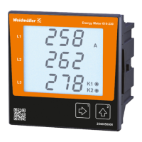
A = current path
V = voltage path
Indication of the phase (L1/L2/L3) with
overrange. The current phase l4 over-
ranges occur as shown in the gure below.
Examples
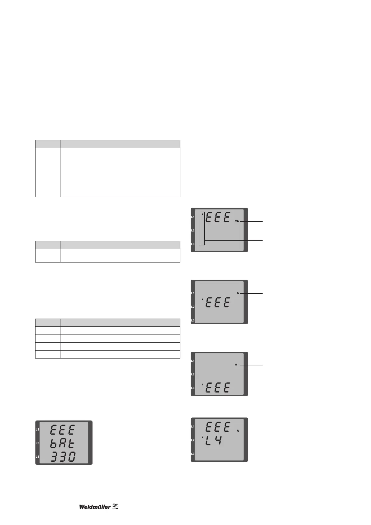
A = current path
Fig.: Indication of the overrange in the current path of phase 2
(l2).
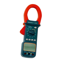
V = voltage path
Fig.: Indication of the overrange in voltage path L3.
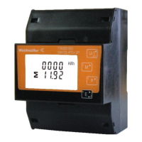
Fig.: Indication of the overrange in current path l4.