REMOVING MAIN BEARING
CASE
1.
Remove the two mounting bolts for main bearing case assembly
2.
Detach the main bearing
case,
being careful with the side and crankshaft bearings.
3.
Detach the other bearing cases 2 and 3
in
the same method.
Be
careful not to mix them
up.
NOTE
FOR
REASSEMBLIING: Clean the oil holes
in
the main bearing
case.
Install the main
bearing case with their side marks toward the flywheel. Be sure to install main bearing 1 with its
oil grove facing outward. Tighten the bearing case bolts 1 to 2 to 24
Nm
(2.0
to 2.4
kgfOm,
15
to
17
ft-Ibs).
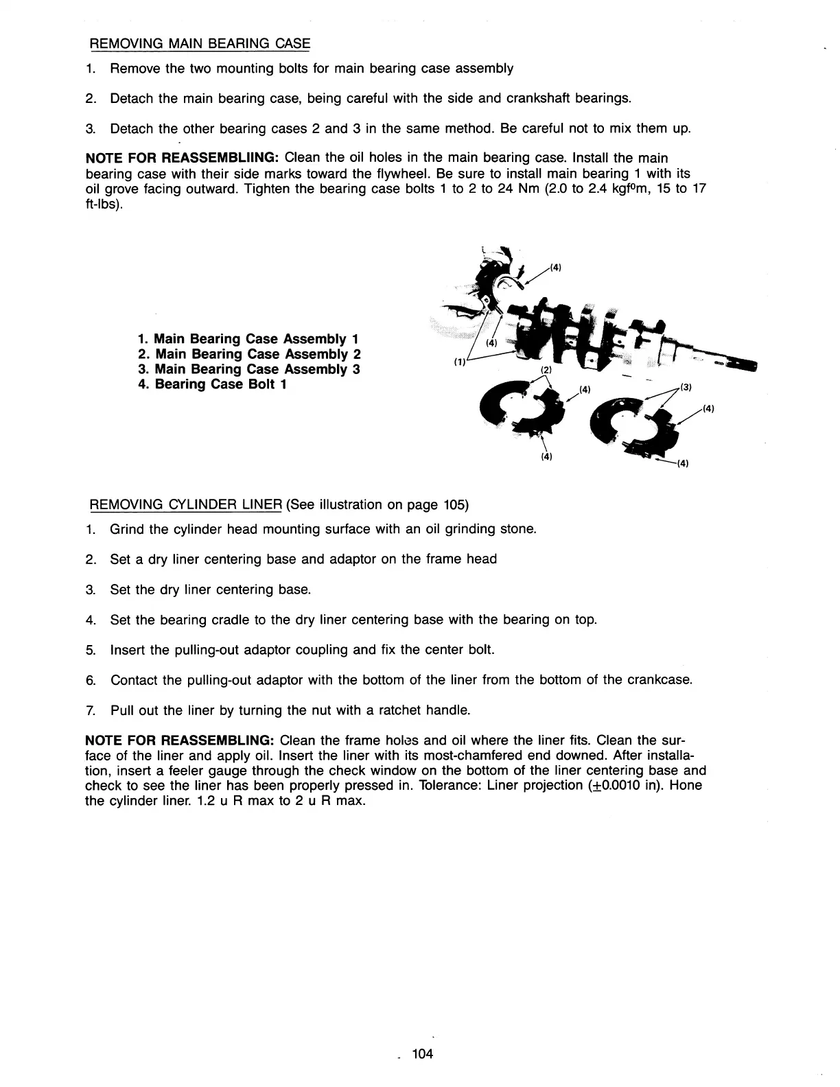
1.
Main Bearing Case Assembly 1
2. Main Bearing Case Assembly 2
3.
Main Bearing Case Assembly 3
4.
Bearing Case
Bolt
1
REMOVING CYLINDER LINER (See illustration
on
page
105)
1.
Grind the cylinder head mounting surface with
an
oil grinding stone.
2.
Set a dry liner centering base and adaptor
on
the frame head
3.
Set the dry liner centering base.
4.
Set the bearing cradle to the dry liner centering base with the bearing
on
top.
5.
Insert the pulling-out adaptor coupling and fix the center bolt.
6.
Contact the pulling-out adaptor with the bottom of the liner from the bottom of the crankcase.
7.
Pull out the liner
by
turning the nut with a ratchet handle.
NOTE
FOR
REASSEMBLING: Clean the frame
holl3s
and oil where the liner fits. Clean the sur-
face of the liner and apply oil. Insert the liner with its most-chamfered end downed. After installa-
tion, insert a feeler gauge through the check window on the bottom of the liner centering base and
check to see the liner has been properly pressed in. Tolerance: Liner projection (±0.0010 in). Hone
the cylinder liner.
1.2
u R max to 2 u R max.
104