ALTERNATOR REPAIR PROCEDURE
General
The following instructions are presented
as
a general overall procedure for complete disassembly
of
an
alternator.
However,
it should be
pOinted
out that following the complete procedure whenever
a repair is necessary will
seldom, if
ever,
be
required.
In
cases where the causes of the
malfunction are known, it is only necessary to follow that portion of the procedure directly related
to resolving the problem. Similarly, when the reasons for the malfunction are uncertain, it will
be
necessary to follow the procedure in greater depth in order to isolate and correct the problem.
The following troubleshooting diagram should help identify some of the more common problems to
concentrate on during the
overhaul/repair procedure.
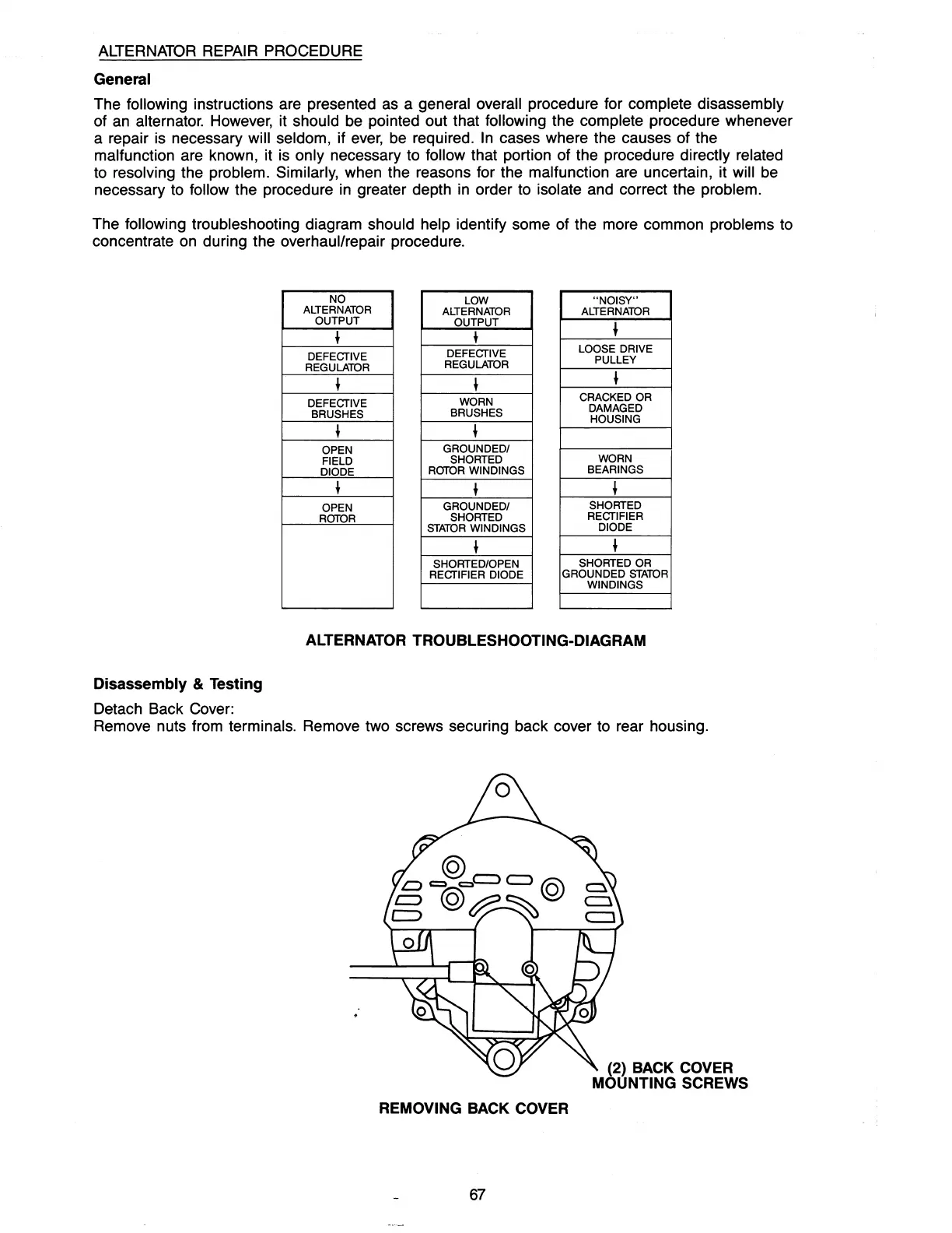
Disassembly
& Testing
Detach Back Cover:
NO
LOW
"NOISY"
ALTERNATOR
ALTERNATOR ALTERNATOR
OUTPUT
~
OUTPUT
+
~
DEFECTIVE
REGULATOR
~
DEFECTIVE
REGULATOR
~
LOOSE DRIVE
PULLEY
~
DEFECTIVE
BRUSHES
WORN
BRUSHES
CRACKED OR
DAMAGED
HOUSING
~
~
OPEN
FIELD
DIODE
GROUNDEDI
SHORTED
ROTOR WINDINGS
WORN
BEARINGS
~
~
~
OPEN
ROTOR
GROUNDEDI
SHORTED
STATOR
WINDINGS
SHORTED
RECTIFIER
DIODE
~
~
SHORTED/OPEN
SHORTED OR
RECTIFIER DIODE
GROUNDED
STATOR
WINDINGS
ALTERNATOR TROUBLESHOOTING-DIAGRAM
Remove nuts from terminals. Remove two screws securing back cover to rear housing.
REMOVING BACK COVER
67
(2) BACK COVER
MOUNTING SCREWS