Test
No.2
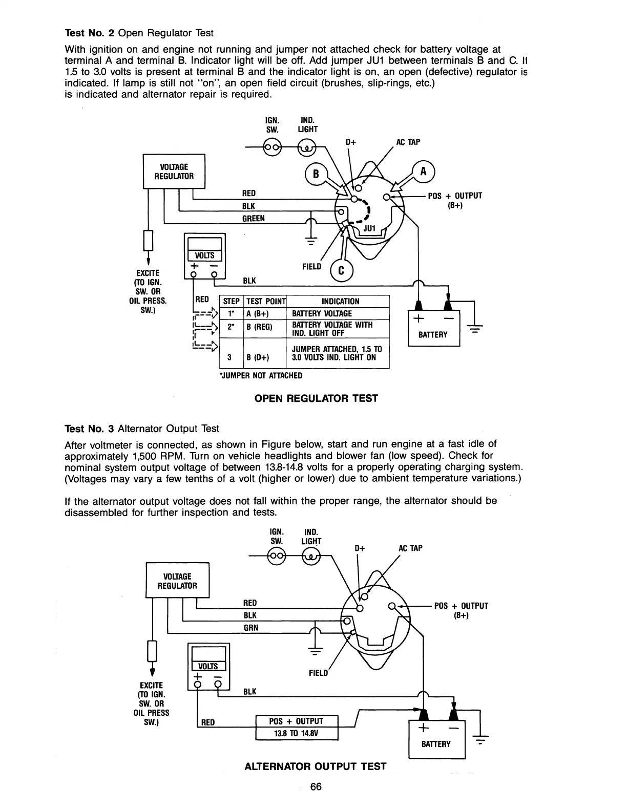
Open Regulator
Test
With ignition
on
and engine not running and jumper not attached check for battery voltage at
terminal A and terminal
B.
Indicator light will be off. Add jumper JU1 between terminals
Band
C.
11
1.5 to
3.0
volts
is
present
at
terminal B and the indicator light is on,
an
open (defective) regulator
is
indicated. If lamp
is
still not "on",
an
open field circuit (brushes, slip-rings, etc.)
is indicated and
alternator repair is required.
VOIJAGE
REGULATOR
IGN.
IND.
sw.
LIGHT
RED
f"\.o~--
POS
+
OUTPUT
EXCITE
(TO
IGN.
sw.
OR
OIL
PRESS.
sw.)
I
VOIJS
I
+
-
REO
--"
1'---">
IL
__
">
:r--~
~=="v
STEP
1-
2-
3
BLK
GREEN
BLK
TEST
POIN
INOICATION
A
(B+)
BATTERY
VOIJAGE
B
(REG)
BATTERY
VOIJAGE
WITH
IND.
LIGHT
OFF
JUMPER
ATTACHED,
1.5
TO
B (0+)
3.0
VOLTS
IND.
LIGHT
ON
-JUMPER
NOT
ATTACHED
OPEN REGULATOR TEST
Test No. 3 Alternator Output
Test
(B+)
BATTERY
After voltmeter is connected, as shown
in
Figure below, start and run engine at a fast idle of
approximately 1,500 RPM.
Turn
on
vehicle headlights and blower fan (low speed). Check for
nominal system output voltage of between 13.8-14.8 volts for a properly operating charging system.
(Voltages may vary a few tenths of a volt (higher or lower) due to ambient temperature variations.)
If the alternator output voltage does not fall within the proper range, the alternator should be
disassembled for further inspection and tests.
VOIJAGE
REGULATOR
EXCITE
(TO
IGN.
sw.
OR
OIL
PRESS
sw.)
I
VOIJS
I
+ -
RED
IGN.
IND.
sw.
LIGHT
RED
BLK
GRN
BLK
POS
+
OUTPUT
13.8
TO
14.8V
ALTERNATOR OUTPUT TEST
66
0-*--
POS
+
OUTPUT
(B+)
BATTERY
-
 Loading...


