CHECKING CONNECTING ROD ALIGNMENT
1.
Remove the connecting
rod
crank pin bearing and tighten the
rod
bolts.
2.
Set the connecting
rod
to a connecting
rod
aligner.
3.
Place the gauge
on
the piston pin. Measure the gap between the pin of the gauge and the flat
surface of the aligner.
4.
If the measurement exceeds the allowable limit, replace
IMPORTANT: Because
the
1.0.
of
the
connecting
rod small end
bushing
is
used as
the
basis
for
this
check,
check
it
is
not
worn beforehand. See
engine
specifications.
CRANKSHAFT
CHECKING CRANKSHAFT ALIGNMENT
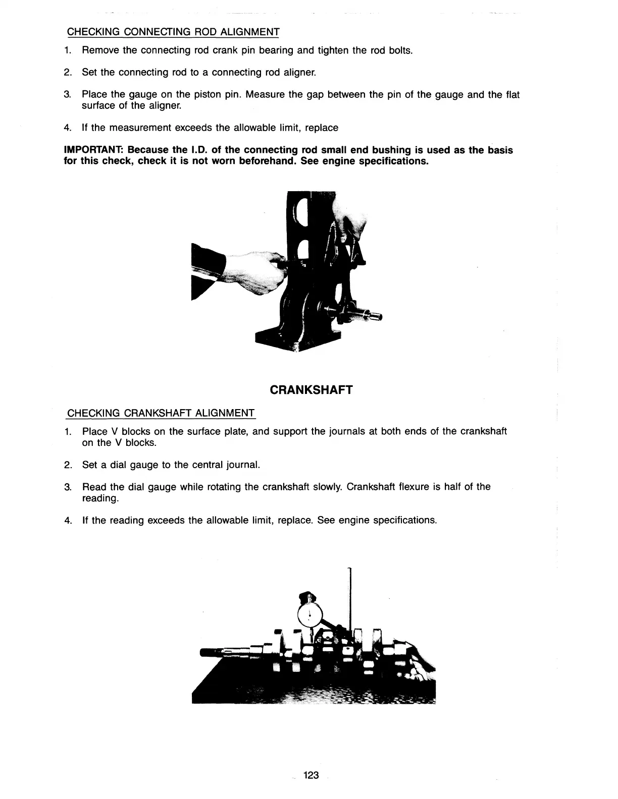
1.
Place V blocks
on
the surface plate, and support the journals at both ends of the crankshaft
on
the V blocks.
2.
Set a dial gauge to the central journal.
3.
Read the dial gauge while rotating the crankshaft slowly. Crankshaft flexure is half of the
reading.
4.
If the reading exceeds the allowable limit, replace. See engine specifications.
123