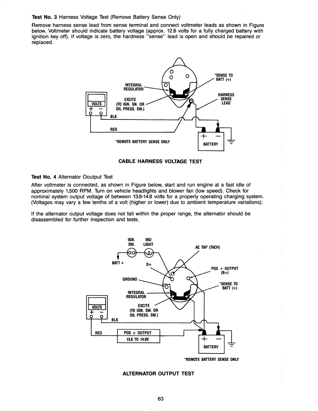
Test No. 3 Harness Voltage Test (Remove Battery Sense Only)
Remove harness sense lead from sense terminal and connect voltmeter leads as shown in Figure
below. Voltmeter should indicate battery voltage (approx. 12.6 volts for a fully charged battery with
ignition key off).
If voltage is zero, the hardness
"sense"
lead is open and should be repaired
or
replaced.
I
voas
I
+ -
INTEGRAL
REGULATOR
EXCITE
(TO
IGN.
SN.
OR
OIL
PRESS.
SW.)
~-f--I
BLK
RED
·REMOTE
BATTERY
SENSE
ONLY
CABLE HARNESS
VOLTAGE
TEST
Test No. 4
Alternator Ooutput Test
BATTERY
After voltmeter is connected, as shown in Figure below, start and run engine at a fast idle of
approximately 1,500 RPM.
Turn
on vehicle headlights and blower fan (low speed). Check for
nominal system output voltage of between
13.8-14.8
volts for a properly operating charging system.
(Voltages may vary a few tenths of a volt (higher or lower) due to ambient temperature variations).
If the alternator output voltage does not fall within the proper range, the alternator should be
disassembled for further inspection and tests.
IGN.
IND
SW.
LIGHT
INTEGRAL
--~
...
I
was
I
REGULATOR
+ -
BLK
RED
POS
+
OUTPUT
13.8
TO
14.BV
BATTERY
·SENSE
TO
BATT
(+)
·REMOTE
BATTERY
SENSE
ONLY
ALTERNATOR OUTPUT TEST
63