Operation0520−1/A1
Winterthur Gas & Diesel Ltd.
2/ 4
5) Replace the defective VCU or the hydraulic pipe (see the Maintenance Manual
5612−1 and 8460−1).
6) Torque the drain screw (2) to 200 Nm.
7) Set to on the bearing oil pump.
8) Cut in the injection (see 0510−1, paragraph 2).
9) In the remote control, use the parameter Exv. A/M Cmd to set the VCU on the
related cylinder to Auto (see 4002−3 paragraph 1 and paragraph 1.1).
10) Connect the electrical connections to the rail valve (5).
11) Do a visual check for leaks.
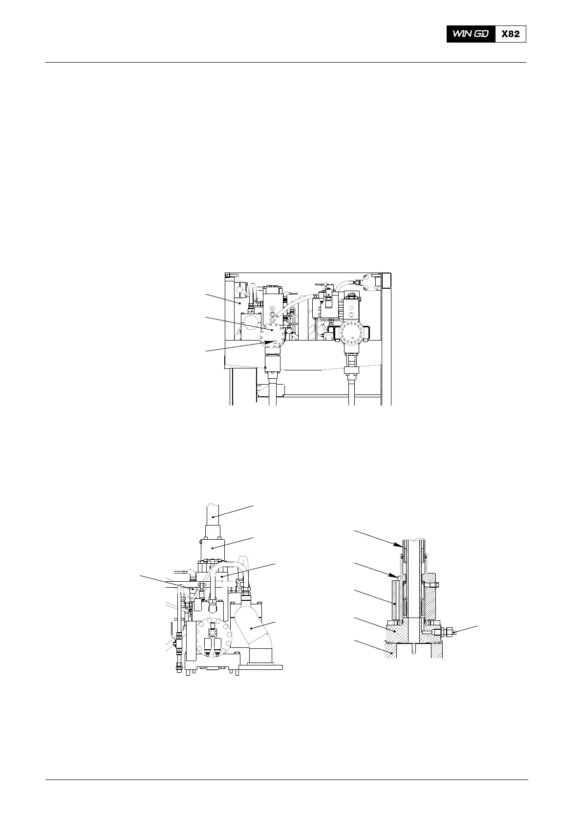
DRIVING END
8
1
2
018.104/09
Fig. 1: Servo Oil Rail
1 Servo oil rail 4.11 8 Rail unit
2 Drain screw 4.82
WCH01206
WCH01207
4
7
3
6
5
4
6
9
3
10
11
Fig. 2: Exhaust Valve Control Unit
3 Exhaust valve control unit 4.10 7 Screw
4 Hydraulic pipe 4.66 9 Servo oil return pipe 4.63
5 Rail valve 4.76 10 Cover
6 Flange 11 Oil leakage pipe
Operation with Exhaust Valve Control Unit Cut Out
2014