Operation0850−1/A1
Winterthur Gas & Diesel Ltd.
14/ 39
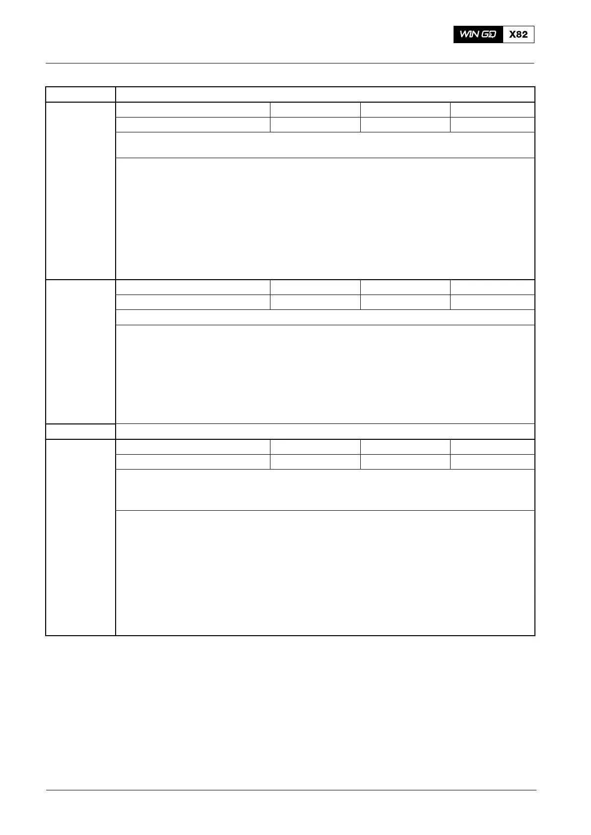
Failure Text
ME exhaust valve #nn position meas. fail. (ID 71)
FCM−20 No. LED Failure ID Display
Indication #01 to #08 Ex.D or Ex.F 71 71
Cause Sensors ZT5421C to 27C (driving end) signal < 2 mA or > 22 mA (failure signal is released
after 3 seconds).
Procedure ⇒ In the related terminal box E95.21 to E95.34 at the cylinder cover, make sure that the plug has
no damage and is connected correctly.
⇒ Make sure that the related cables to the sensor and FCM−20 (plug X24, terminals 68 to 72)
have no damage and are connected correctly.
⇒ In the related FCM−20 and in the terminal box, make sure that the cables and connections
have no damage and are connected correctly.
⇒ If necessary, replace the related sensor.
⇒ If the failure shows at intervals, temporarily disconnect the plug on the terminal box until a re-
pair is possible.
FCM−20 No. LED Failure ID Display
Indication #01 to #08 Ex.D or Ex.F 71 71
Cause The sensor power supply has a short circuit (red LED)
Procedure ⇒ Make sure that the related cables to the sensor and the FCM−20 (plug X24, terminals 68 to 72)
have no damage and are connected correctly.
⇒ Make sure that the cables and connections in the related FCM−20 and in the terminal box
have no damage and are correctly connected.
⇒ If necessary, replace the related sensor.
⇒ If the failure shows at intervals, replace the cable-plug assembly to E95 with the spare.
Remark: Temporarily disconnect the plug X24 on the terminal box until a repair is possible.
Failure Text WECS module FCM−20 #00 fail. (ID 94)
FCM−20 No. LED Failure ID Display
Indication #00 (E90) Fail 94 94
Cause Missing communication on CAN S1 and CAN S2 bus on FCM−20 #00
The remaining FCM−20 in the system on each S-bus did not receive a heartbeat signal from
this module.
Procedure ⇒ Make sure that the FCM−20 #00 is is set to on.
⇒ Use a multimeter to do a check of the 24 VDC power supply in E85 and E90.
⇒ If there is a 24 VDC power supply, make sure that the CAN-S bus connections on FCM−20 #00
(plugs X22 and X23, terminals 49 / 50 and plug X23 terminals 57 / 58) are connected correctly.
⇒ If installed, make sure that the terminating resistors (120 ohm) are serviceable.
⇒ Replace the online spare FCM−20 if necessary
Remark: If a service computer is connected to CAN M #0, it is possible that there will be no
communication.
For ID 95 to ID 0.3, see the procedures for ID 94 above.
2014
Failures and Defects of WECS Components
 Loading...


