Operation
0850−1/A1
Winterthur Gas & Diesel Ltd.
25/ 39
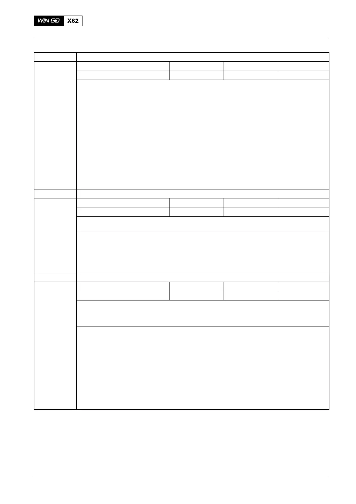
Failure Text
ME crank angle #1 / TDC high shift (ID 63)
FCM−20 No. LED Failure ID Display
Indication #05 BI1 63 63
Cause
The difference between the TDC pick-up and the crank angle sensor #1 is 4.0_ CA
The crank angle sensor or toothed belt has moved.
Remark: No failure shown at shut-down
Procedure ⇒ Do a check for an incorrect TDC offset adjustment in flexView.
⇒ Adjust to get the correct distance between the pick-up and the flywheel tooth (4 mm).
⇒ Do a check of the crank angle sensor drive.
⇒ Make sure that the CAS#1 is in the correct position (at TDC #1).
⇒ Do a check of the belt condition.
⇒ Do a check of the crank angle sensor offset adjustment in flexView.
⇒ Do a CAS trend in flexView.
⇒ If necessary, replace CAS #1.
Failure Text ME crank angle #1 / TDC high shift (ID 63)
FCM−20 No. LED Failure ID Display
Indication #05 BI1 63 63
Cause
The difference between the TDC pick-up and the crank angle measurement system #1 is 4.0_
CA. The crank angle sensor or toothed belt has moved.
Procedure ⇒ Do a check for an incorrect TDC offset adjustment in flexView.
⇒ Adjust to get the correct distance between the pick-up and the flywheel tooth (4 mm).
⇒ Stop the engine, then use the turning gear and do a CAS trend in flexVIew.
⇒ Make sure that each trend line for CAS#1 and CAS#2 is the same.
Failure text ME crank angle #2 / TDC high shift (ID 64)
FCM−20 No. LED Failure ID Display
Indication #05 BI1 64 64
Cause
The difference between the TDC pick-up and the crank angle sensor #1 is 4.0_ CA.
The crank angle sensor or toothed belt has moved
Remark: No failure shown at shut-down
Procedure ⇒ Do a check for an incorrect TDC offset adjustment in flexView.
⇒ Adjust the get the correct distance between the pick-up and the flywheel tooth (4 mm).
⇒ Do a check of the crank angle sensor drive.
⇒ Make sure that the CAS#2 is in the correct position (at TDC #1).
⇒ Do a check of the belt condition.
⇒ Do a check of the crank angle sensor offset adjustment in flexView.
⇒ Do a CAS trend in flexView.
⇒ If necessary, replace CAS #2
2014
Failures and Defects of WECS Components
 Loading...


