Operation4003−3/A1
Winterthur Gas & Diesel Ltd.
2/ 21
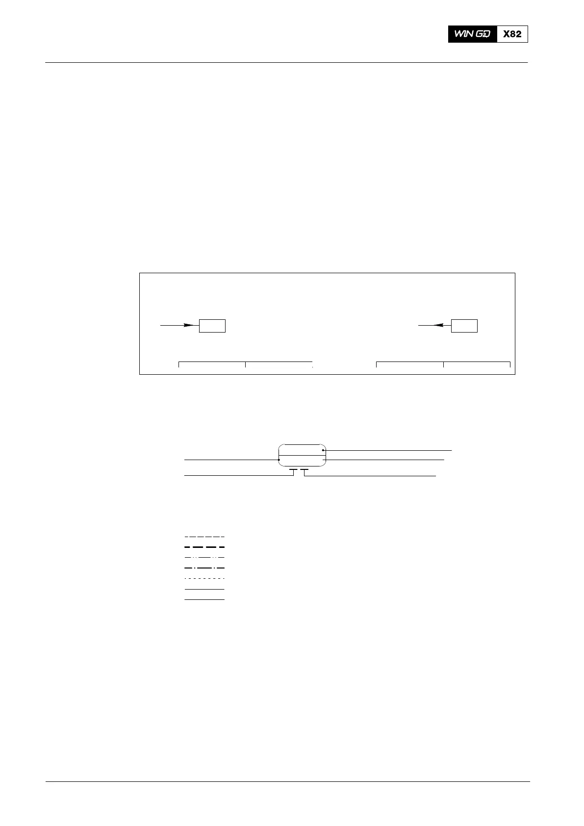
1.1 How to Read the Diagrams
Each diagram has a Path No. range given to the system part. The Path No. range is
divided into 10 sections on the right side of the page. These path numbers give the
connections between related diagrams.
In the example below, the control air pipe that has the number 38 (page 3) goes to the
target path No. 51 (found on page 5).
Where two path numbers that are the same are shown, letter indications are used.
For example, on page 3, there are the numbers 38 and 38A. The number 38 is
Control Air and the number 38A is Air Spring Air.
1.2 Example
38 39
38
119
119118
Page 3 Page 9
38
CONTROL AIR
CONTROL AIR
Path No.
The interfaces to the remote control, local alarm and instruments have symbols (see
the example below).
Code letter for systems
Signal from / to engine
ZS
5123C
Code letter for function identification
Function Group
Consecutive Number
Note: Systems are drawn for engine in the STOP position with unpressurized
circuits.
Low pressure oil circuits
High pressure oil circuits
Low pressure fuel circuits
High pressure fuel circuits
Heating
Control air circuits
Starting air circuits
2014