Operation5591−1/A1
Winterthur Gas & Diesel Ltd.
2/ 2
016.896/08
16
111
14
10
17
13
15
12
Data from RT−flex82C
WCH01126
865
OP
2
OB
4
3
OB
9
7
OI
2
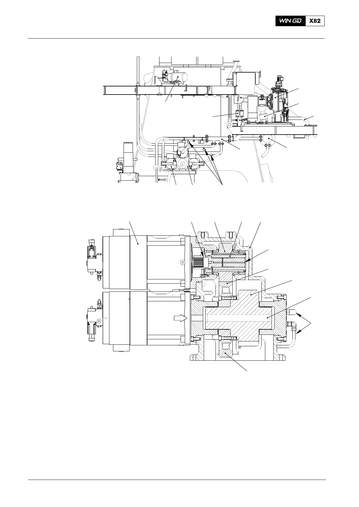
Fig. 1: Location Servo Pump Unit with Dynex Servo Oil Pump
1 Servo pump unit 11 Flow sensor 4.54
2 Servo oil pump 4.15 12 Stop valve 4.37
3 (Driving) gear wheel 4.43 13 Oil inlet pipe on exhaust side
4 Gear wheel 4.44 14 Stop valve 4.80
5 Pinion 4.45 15 Supply pipe 4.51
6 Shaft 4.50 16 Servo oil service pump 4.88
7 Intermediate wheel 4.41 17 Flushing oil drain pipe
8 Casing OB Oil bore
9 Supply pipe OI Oil inlet
10 Automatic filter 4.20 OP Overload protection (specified break point)
2014
Servo Pump Unit with Dynex Servo Oil Pump