Operation8016−1/A1
Winterthur Gas & Diesel Ltd.
12/ 12
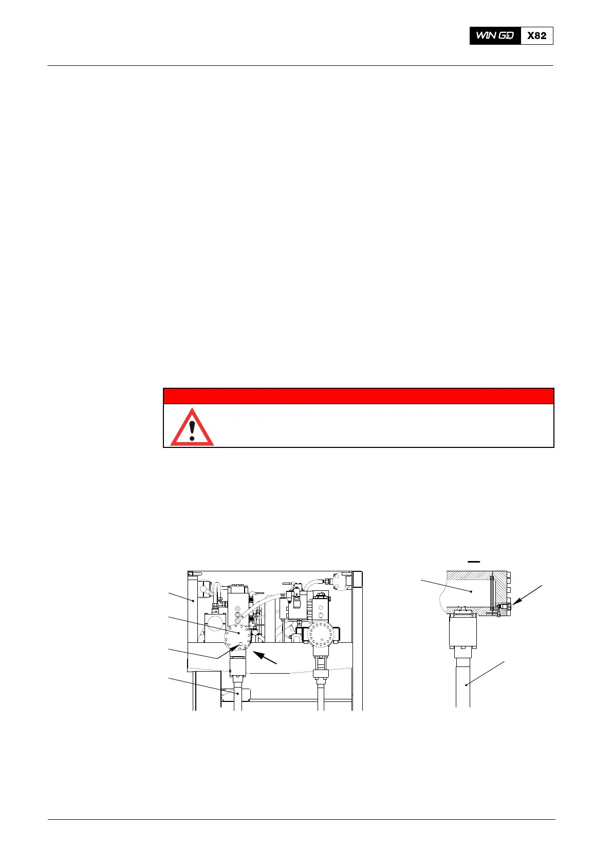
6. Servo Oil Rail − Fill and Drain
6.1 Fill and Vent
1) Make sure that the stop valves (14, Fig. 3) and (15) (upstream and downstream
of the automatic filter (1) are open.
2) Make sure that the drain screw (2, Fig. 6) (in the servo oil rail (1)) has a torque of
200 Nm.
3) Start the bearing oil pump.
Bearing oil flows through the automatic filter to the servo oil pumps. The servo oil
pumps supply oil to the HP servo oil pipes (3). The supply pressure opens the
non-return valves and oil flows into the servo oil rail (1). From the servo oil rail, the oil
flows through hydraulic pipes to the exhaust valve control units and into the exhaust
valve housings. Orifices vent the full system.
For more data, see 2751−1 Exhaust Valve.
Note: To do a function check of the exhaust valve movement, or a leak test of
the servo oil system, the servo oil service pump 4.88 must be set to on.
6.2 Drain
WARNING
Injury Hazard: Always use gloves and safety goggles when you
do work on hot components. When you loosen the screw plugs,
high pressure oil can come out as a spray and cause injury.
To drain the servo oil rail (1, Fig. 6), do the procedure that follows:
D Carefully open the drain screw (2).
D Keep the drain screw (2) open until all the oil has drained.
D Torque the drain screw (2) to 200 Nm.
DRIVING END
018.104/09
4
3
2
1
2
3
1
I
I
WCH01151
Fig. 6: Servo Oil Rail
1 Servo oil rail 4.11 3 HP servo oil pipe 4.55
2 Drain screw 4.82 4 Rail unit
2014
Lubricating Oil System 6-cylinders to 8-cylinders