Operation
9314−1/A1
Winterthur Gas & Diesel Ltd.
3/ 3
3
ENGINE ROOM CONTROL ROOM
WCH02858
2
4
6
PS
7
9
PS
7
AM
SS
9
8
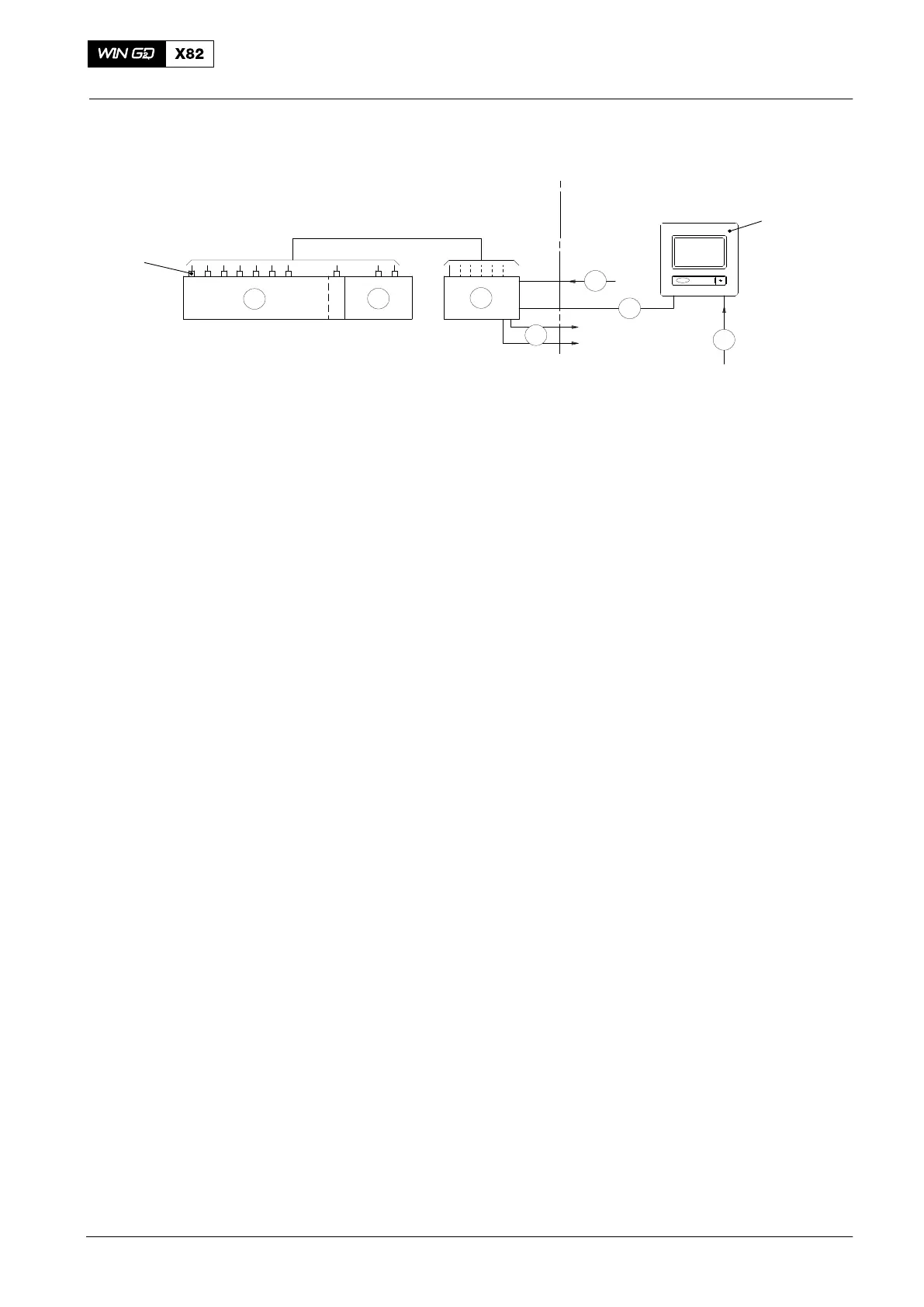
Fig. 2: Schematic Diagram
2 Control unit E15.1 8 Control panel
3 Sensor 9 Communications cable (Modbus)
4 Fuel pump unit PS Power supply
6 Crankcase and gearbox AM to alarm and monitoring system
7 Power cable SS to safety system
2014-09
Oil Mist Detector 6-cylinders to 8-cylinders