Maintenance1132−1/A1
RT-flex58T-D
Winterthur Gas & Diesel Ltd.
2/ 3
3. Tensioning the elastic studs
After fitting the main bearing cover as described in 1132−2, elastic studs 1 are to be
tensioned as follows:
⇒ Place both double pre-tensioning jacks 94114 onto elastic studs 1 for the main
bearing (Fig. ’C’).
⇒ Connect both double pre-tensioning jacks by HP hoses 94935, connection
block 94934 and hydraulic distributor 94932 with hydraulic unit 94942 (ar-
rangement see Fig. ’C’).
⇒ Screw on nuts 4 of the double pre-tensioning jacks till piston 5 fully seat on
cylinders 6 (Fig. ’B’).
The pistons are fully down on the cylinders when distance ’L’ is about 23 mm, mea-
sured from the top of the piston to the upper edge of cover 7.
Check the oil level in hydraulic unit 94942.
⇒ Actuate the hydraulic unit, adjust the
pressure to 1500 bar and keep it
constant.
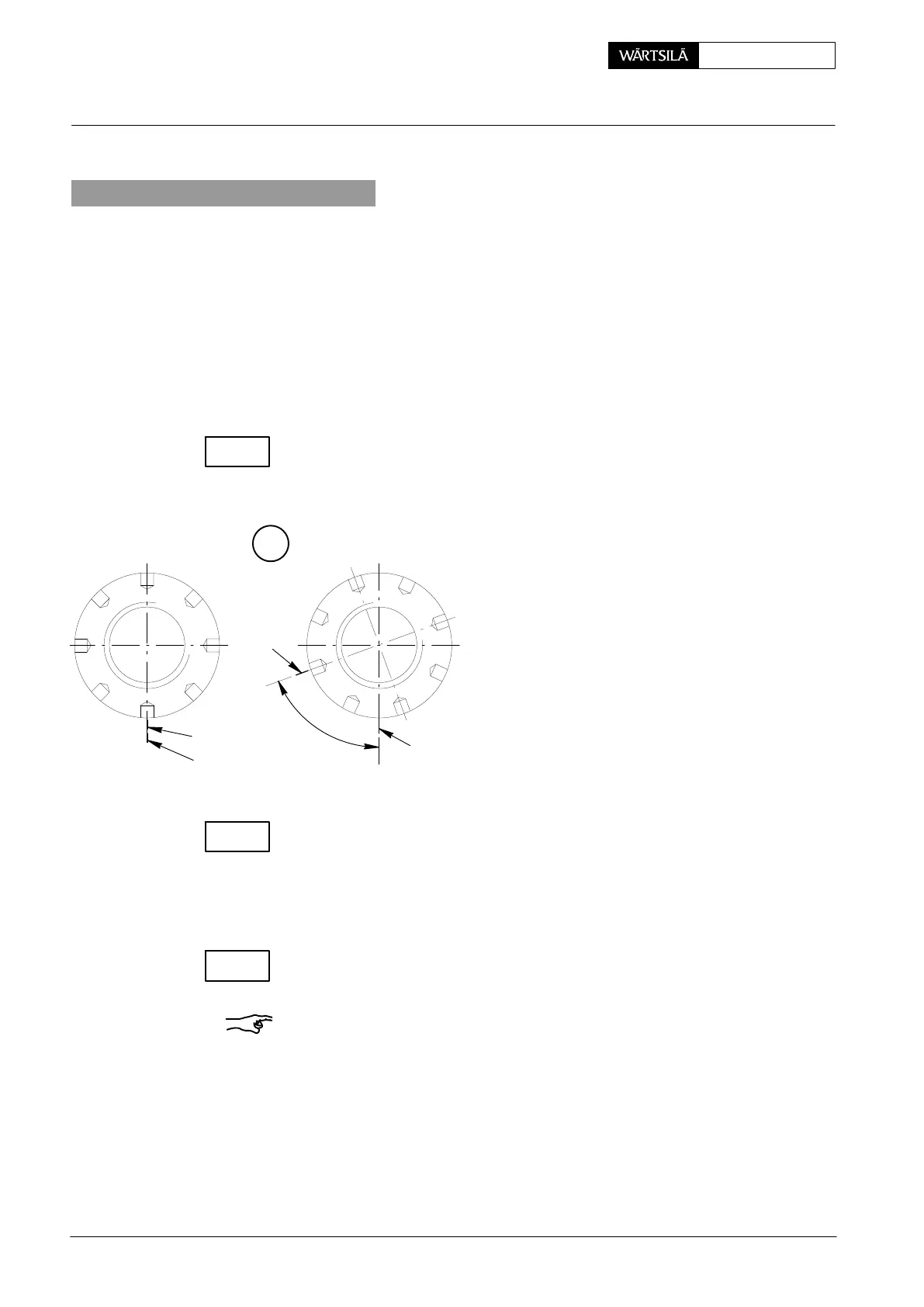
⇒ Mark the position of nuts 3 against
bearing cover = 1
st
step (Fig. ’A’).
⇒ Tighten all nuts 3 with round bar ’RS’
until firmly seated.
TIGHTENING
ANGLE
1
ST
STEP 2
ND
STEP
009.668/02
A
y
x
y
x
010.357/02
Using feeler gauge 94122 inserted in slot ’KO’, check if there is no clearance at
hand between the nuts and the seating surfaces (2
nd
step).
No clearance must also be at hand between main bearing girder 8 and main bear-
ing cover 2 (Fig. ’C’)!
⇒ Release pressure to zero at the hydraulic unit and then remove both double
pre-tensioning jacks.
Check if all the nuts have been turned by about the same value.
Finally check the horizontal and vertical clearance by means of special feeler
gauge 94123 (see Clearance Table 0330−1 ’Crankshaft and main bearing’).
Remark: All main bearing clearance values are valid only with tightened tie rods
and elastic studs.
Main Bearing: Loosening and Tensioning of Elastic Studs
2013
CHECK
CHECK
CHECK
 Loading...


