EasyManua.ls Logo

Wittenstein cyber motor simco SIM2002D - Page 25

Default Icon
51 pages
Print Icon
To Next Page IconTo Next Page
To Previous Page IconTo Previous Page
Loading...
Operation Manual simco
®
drive
Revision: 11a 4022-D033499 en-23
日本語
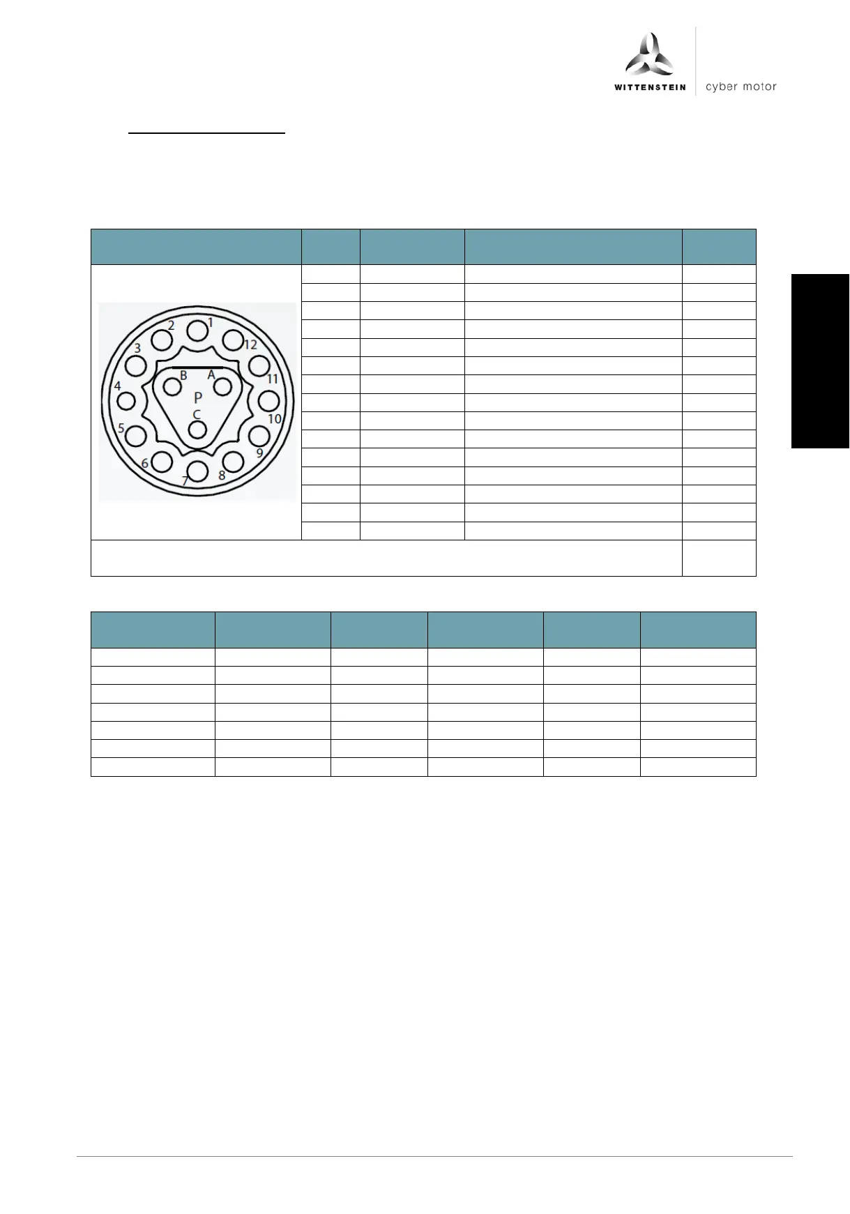
6.3.11 X9: Motor connection
The plug may only be inserted when the drive amplifier is in a de-energized state.
The encoder supply (pin 1 + 2) and encoder signals (pin 3 .. 8) are galvanically
isolated from the power of the drive amplifier.
Figure
Pin
no.
Signal
name
Function
Input/
output
A
PHASE_U
Motor phase U
Output
B
PHASE_V
Motor phase V
Output
C
PHASE_W
Motor phase W
Output
1
GND
Reference ground
-
2
VCC5
Encoder voltage 5 VDC
Output
3
CLOCK+
Clock signal
Output
4
CLOCK-
Clock signal inverted
Output
5
DATA+
Data signal
Input
6
DATA-
Data signal inverted
Input
7
N.C.
Input
8
N.C.
Input
9
TEMP+
Motor temperature sensor +
Input
10
TEMP-
Motor temperature sensor -
Input
11
BRAKE+
Holding brake +
Output
12
BRAKE-
Holding brake -
Output
Plug type on drive amplifier: Intercontec, itec 915, 15-pin, female
(EEGA 205 NN00 00 0012 000)
Connection
Properties
Unit
Minimum
value
Nominal
value
Maximum
value
PHASE_x
Current
Aeff
10
20
VCC5
Voltage
V DC
4,5
5
5,5
Current
mA DC
250
BRAKE+/-
Voltage
V DC
24
Current
A DC
0,8

Table of Contents